Pin description general description – Rainbow Electronics MAX1617A User Manual
Page 6
MAX1617A
Remote/Local Temperature Sensor
with SMBus Serial Interface
6
_______________________________________________________________________________________
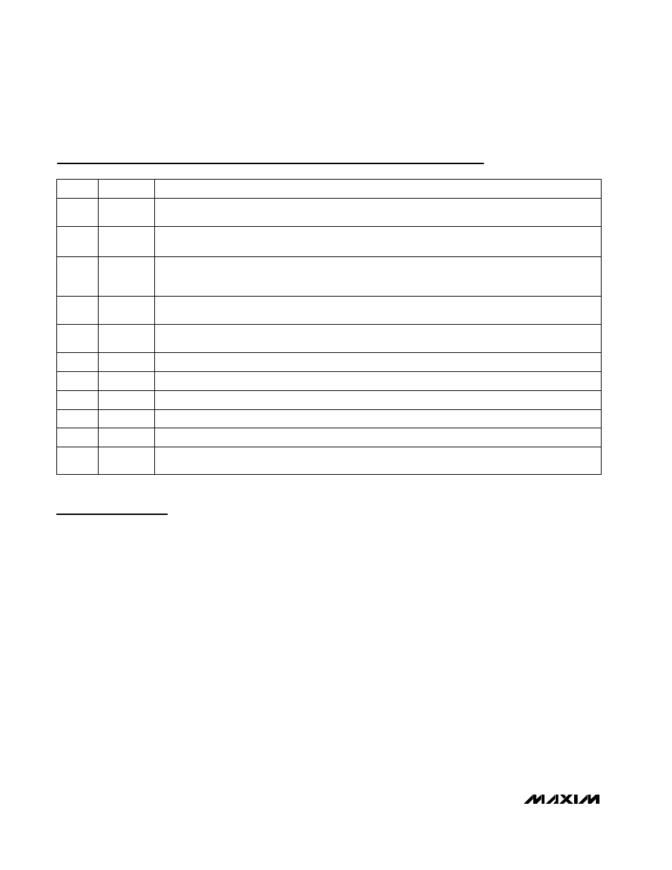
Pin Description
General Description
The MAX1617A (patents pending) is a temperature
sensor designed to work in conjunction with an external
microcontroller (µC) or other intelligence in thermostat-
ic, process-control, or monitoring applications. The µC
is typically a power-management or keyboard con-
troller, generating SMBus serial commands by “bit-
banging” general-purpose input/output (GPIO) pins or
via a dedicated SMBus interface block.
Essentially an 8-bit serial analog-to-digital converter
(ADC) with a sophisticated front end, the MAX1617A
contains a switched current source, a multiplexer, an
ADC, an SMBus interface, and associated control logic
(Figure 1). Temperature data from the ADC is loaded
into two data registers, where it is automatically com-
pared with data previously stored in four over/under-
temperature alarm registers.
ADC and Multiplexer
The ADC is an averaging type that integrates over a
60ms period (each channel, typical) with excellent
noise rejection.
The multiplexer automatically steers bias currents
through the remote and local diodes, measures their
forward voltages, and computes their temperatures.
Both channels are automatically converted once the
conversion process has started, either in free-running
or single-shot mode. If one of the two channels is not
used, the device still performs both measurements, and
the user can simply ignore the results of the unused
channel. If the remote diode channel is unused, tie DXP
to DXN rather than leaving the pins open.
The DXN input is biased at 0.65V above ground by an
internal diode to set up the analog-to-digital (A/D)
inputs for a differential measurement. The worst-case
DXP–DXN differential input voltage range is 0.25V to
0.95V.
SMBus Serial-Data Input/Output, Open Drain
SMBDATA
12
SMBus Serial-Clock Input
SMBCLK
14
Hardware Standby Input. Temperature and comparison threshold data are retained in standby mode.
Low = standby mode, high = operate mode.
STBY
15
SMBus Address Select Pin (Table 8). ADD0 and ADD1 are sampled upon power-up. Excess capacitance
(>50pF) at the address pins when floating may cause address-recognition problems.
ADD1
6
Ground
GND
7, 8
SMBus Slave Address Select Pin
ADD0
10
SMBus Alert (interrupt) Output, Open Drain
ALERT
11
Combined Current Sink and A/D Negative Input. DXN is normally biased to a diode voltage above
ground.
DXN
4
Combined Current Source and A/D Positive Input for Remote-Diode Channel. Do not leave DXP floating;
tie DXP to DXN if no remote diode is used. Place a 2200pF capacitor between DXP and DXN for noise fil-
tering.
DXP
3
PIN
Supply Voltage Input, 3V to 5.5V. Bypass to GND with a 0.1µF capacitor. A 200
Ω
series resistor is recom-
mended but not required for additional noise filtering.
V
CC
2
No Connection. Not internally connected. May be used for PC board trace routing.
N.C.
1, 5, 9,
13, 16
FUNCTION
NAME