Applications information, Chip information, Table 1. component suppliers – Rainbow Electronics MAX1779 User Manual
Page 14
MAX1779
Low-Power Triple-Output TFT LCD DC-DC
Converter
14
______________________________________________________________________________________
nated by the internal switch resistance and the diode
impedance. Start with 0.1µF ceramic capacitors.
Smaller values may be used for low-current applica-
tions.
Charge-Pump Output Capacitor
Increasing the output capacitance or decreasing the
ESR reduces the output ripple voltage and the peak-to-
peak transient voltage. Use the following equation to
approximate the required capacitor value:
C
PUMP
≥ [I
PUMP
/ (125kHz
✕
V
RIPPLE
)]
Charge-Pump Input Capacitor
Use a bypass capacitor with a value equal to or greater
than the flying capacitor. Place the capacitor as close
to the IC as possible. Connect directly to PGND.
Rectifier Diode
Use Schottky diodes with a current rating equal to or
greater than 4 times the average output current, and a
voltage rating at least 1.5 times V
SUPP
for the positive
charge pump and V
SUPN
for the negative charge pump.
PC Board Layout and Grounding
Carefully printed circuit layout is extremely important to
minimize ground bounce and noise. First, place the
main boost converter output diode and output capacitor
less than 0.2in (5mm) from the LX and PGND pins with
wide traces and no vias. Then place 0.1µF ceramic
bypass capacitors near the charge-pump input pins
(SUPP and SUPN) to the PGND pin. Keep the charge-
pump circuitry as close to the IC as possible, using
wide traces and avoiding vias when possible. Locate
all feedback resistive dividers as close to their respec-
tive feedback pins as possible. The PC board should
feature separate GND and PGND areas connected at
only one point under the IC. To maximize output power
and efficiency and to minimize output power ripple volt-
age, use extra wide power ground traces and solder
the IC’s power ground pin directly to it. Avoid having
sensitive traces near the switching nodes and high-cur-
rent lines.
Refer to the MAX1779 evaluation kit for an example of
proper board layout.
Applications Information
LX Charge Pump
Some applications require multiple charge-pump
stages due to low supply voltages. In order to reduce
the circuit’s size and component count, an unregulated
charge pump may be added onto the LX switching
node. The configuration shown in Figure 4 works well
for most applications. The maximum output current of
the low-power charge pumps depends on the maxi-
mum load current that the LX charge pump can provide
and is limited by the following formula:
I
LXPUMP
= ((N + 1)
✕
I
POS
) + (M + I
NEG
)
≤ 5mA
where N is the number of stages in the positive low-
power charge pump, and M is the number of stages in
the negative charge pump. Applications requiring more
output current should not use the LX charge pump, so
they will require extra stages on both low-power charge
pumps. The output capacitor of this unregulated
charge pump needs to be stacked on top of the main
output in order to keep the main regulator stable.
Increasing the integrator capacitor may also be
required to compensate for the additional charge-pump
capacitance on the main regulator loop.
The output capacitor of this unregulated charge pump
needs to be stacked on top of the main output in order
to keep the main regulator stable. Increasing the inte-
grator capacitor may also be required to compensate
for the additional charge-pump capacitance on the
main regulator loop.
Chip Information
TRANSISTOR COUNT: 2846
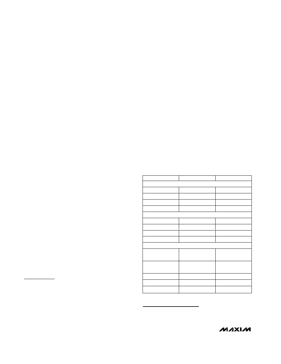
SUPPLIER
PHONE
FAX
INDUCTORS
Coilcraft
847-639-6400
847-639-1469
Coiltronics
561-241-7876
561-241-9339
Sumida USA
847-956-0666
847-956-0702
Toko
847-297-0070
847-699-1194
CAPACITORS
AVX
803-946-0690
803-626-3123
Kemet
408-986-0424
408-986-1442
Sanyo
619-661-6835
619-661-1055
Taiyo Yuden
408-573-4150
408-573-4159
DIODES
Central
Semiconductor
516-435-1110
516-435-1824
International
Rectifier
310-322-3331
310-322-3332
Motorola
602-303-5454
602-994-6430
Nihon
847-843-7500
847-843-2798
Zetex
516-543-7100
516-864-7630
Table 1. Component Suppliers