Detailed description, Pin description – Rainbow Electronics MAX1558H User Manual
Page 7
Detailed Description
The MAX1558/MAX1558H are dual current-limited
switches designed for USB applications. They have two
independent switches, each with its own enable control
input and autoreset function. Each switch has an error-
flag output to notify the USB controller when current-
limit, short-circuit, undervoltage-lockout, or thermal-
shutdown conditions occur (Figure 2). The MAX1558/
MAX1558H operate from a 2.7V to 5.5V supply. Each
output can supply up to 1.2A. Current limit for both
channels is set with one external resistor.
The MAX1558/MAX1558H have independent thermal
shutdown for each switch in the event of a prolonged
overload. An autoreset function monitors the output and
automatically turns the switch on when the overload is
removed. Separate current limiting and thermal-shut-
down circuits permit each switch to operate indepen-
dently, improving system robustness.
MAX1558/MAX1558H
Dual, 3mm x 3mm, 1.2A/Programmable-Current
USB Switches with Autoreset
_______________________________________________________________________________________
7
PIN
NAME
FUNCTION
1
INA
Power Input for OUTA. Connect INA and INB together and bypass with a 0.1µF capacitor to ground.
Load conditions may require additional bulk capacitance to prevent the input from being pulled down.
2
ONA
*(ONA)
Control Input for Switch A. Can be driven higher than IN_ without damage. A logic low turns switch A on
for the MAX1558. A logic high turns switch A on for the MAX1558H.
3
ISET
Current-Limit Adjust for Both Channels. Connect a resistor between 26k
Ω to 60kΩ from ISET to ground to
program the current limit. See Setting the Current Limit in the Applications Information section.
4
ONB
*(ONB)
Control Input for Switch B. Can be driven higher than IN_ without damage. A logic low turns switch B on
for the MAX1558. A logic high turns switch B on for the MAX1558H.
5
INB
Power Input for OUTB. Connect INB and INA together and bypass with a 0.1µF capacitor to ground.
Load conditions may require additional bulk capacitance to prevent the input from being pulled down.
6
OUTB
Power Output for Switch B. Connect a 1µF capacitor from OUTB to ground. The load condition may
require additional bulk capacitance.
7
FLTB
Fault Indicator Output for Switch B. This open-drain output goes low when switch B is in thermal
shutdown or UVLO or in a sustained (>20ms) current-limit or short-circuit condition.
8
GND
Ground
9
FLTA
Fault Indicator Output for Switch A. This open-drain output goes low when switch A is in thermal
shutdown or UVLO or in a sustained (>20ms) current-limit or short-circuit condition.
10
OUTA
Power Output for Switch A. Connect a 1µF capacitor from OUTA to ground. The load condition may
require additional bulk capacitance.
—
PAD
Exposed Pad, Internally Connected to GND. Connect exposed pad to a large copper trace for maximum
power dissipation.
Pin Description
*( ) are for the MAX1558H only.
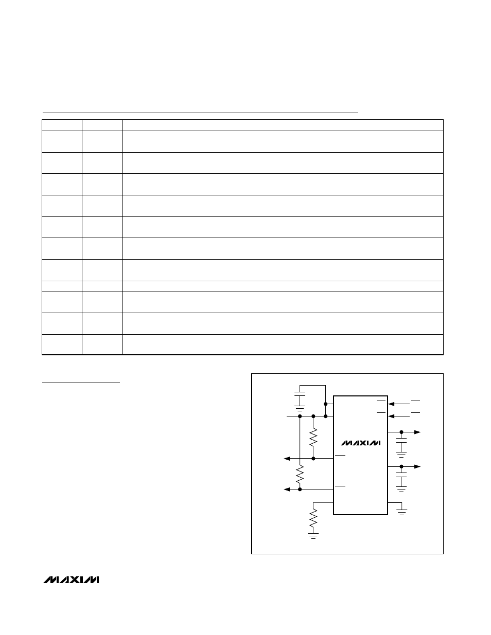
MAX1558
INPUT
2.7V TO 5.5V
INA
INB
ISET
FLTA
FLTB
ONA
ONB
ONA
ONB
OUTA
OUTB
GND
USB
PORT A
USB
PORT B
0.1
µF
100k
Ω
100k
Ω
1
µF*
1
µF*
*USB APPLICATIONS MAY REQUIRE ADDITIONAL
BULK CAPACITANCE
Figure 1. Typical Application Circuit