Rainbow Electronics MAX1558H User Manual
Page 2
MAX1558/MAX1558H
Dual, 3mm x 3mm, 1.2A/Programmable-Current
USB Switches with Autoreset
2
_______________________________________________________________________________________
ABSOLUTE MAXIMUM RATINGS
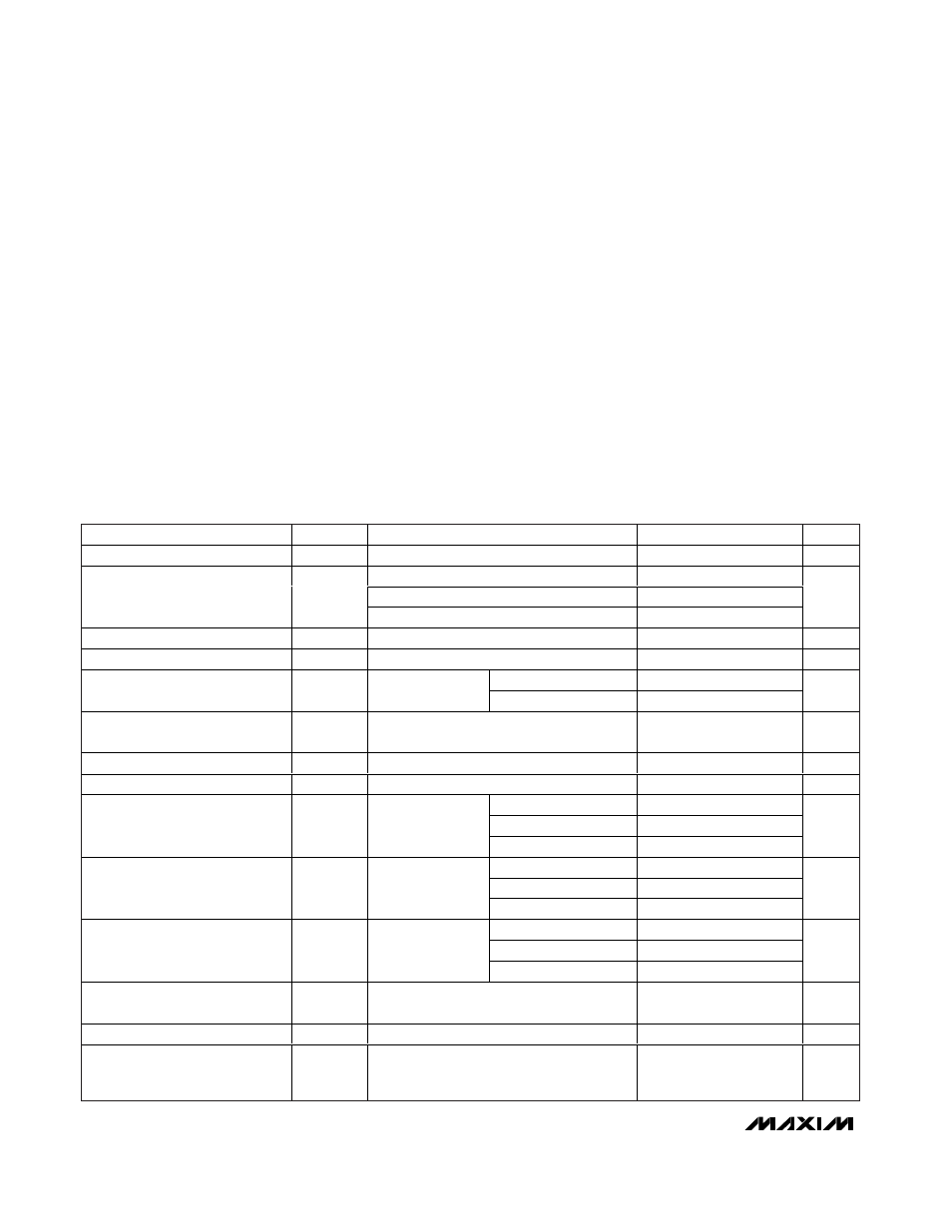
ELECTRICAL CHARACTERISTICS
(V
INA
= V
INB
= 5V, V
ONA
= V
ONB
= 0V (MAX1558), V
ONA
= V
ONB
= 5V (MAX1558H), R
ISET
= 26k
Ω to GND,
T
A
= 0°C to +85°C
,
unless otherwise noted. Typical values are at T
A
= +25
°C.) (Note 3)
Stresses beyond those listed under “Absolute Maximum Ratings” may cause permanent damage to the device. These are stress ratings only, and functional
operation of the device at these or any other conditions beyond those indicated in the operational sections of the specifications is not implied. Exposure to
absolute maximum rating conditions for extended periods may affect device reliability.
IN_, ON_, OUT_, ISET, FLT_ to GND........................-0.3V to +6V
IN_ to OUT_ (when disabled) (Note 1) ........................-6V to +6V
IN_ to OUT_ (when enabled) (Note 2) ............-1.6A to +1.6A
RMS
FLT_ Sink Current................................................................20mA
Continuous Power Dissipation (T
A
= +70°C)
10-Pin TDFN 3mm x 3mm
(derate 24.4mW/
°C above +70°C).............................1952mW
Operating Temperature Range ...........................-40°C to +85°C
Junction Temperature ......................................................+160°C
Storage Temperature Range .............................-65°C to +150°C
Lead Temperature (soldering, 10s) .................................+300°C
PARAMETER
SYMBOL
CONDITIONS
MIN
TYP
MAX
UNITS
Supply Voltage Range
2.75
5.50
V
V
IN_
= 5V, T
A
= +25
°C
55
75
V
IN_
= 3.3V, T
A
= +25
°C
64
Switch On-Resistance
R
ON
V
IN_
= 4.4V, T
A
= 0
°C to +85°C
105
m
Ω
Standby Supply Current
Both switches disabled
3
6
µA
Quiescent Supply Current
Both switches enabled
45
75
µA
V
OUTA
= V
OUTB
= 0V
0.03
10
OUT_ Off-Leakage Current
Switches disabled
V
OUTA
= V
OUTB
= 5V
0.03
µA
Reverse Leakage Current
V
IN_
= 0V, V
OUTA
= V
OUTB
= 5V, both
switches disabled
0.03
µA
Undervoltage-Lockout Threshold
V
UVLO
Rising edge, 3% hysteresis
2.3
2.5
2.7
V
Continuous Load Current
R
ISET
= 26k
Ω
1.2
A
R
ISET
= 26k
Ω
1.20
1.4
1.60
R
ISET
= 39k
Ω
0.80
0.925
1.05
Current-Limit Threshold
V
IN_
- V
OUT_
=
0.5V
R
ISET
= 60k
Ω
0.50
0.6
0.70
A
R
ISET
= 26k
Ω
1.45
2.0
2.60
R
ISET
= 39k
Ω
1.40
Peak Short-Circuit Current Limit
I
SHORT
V
OUT_
= 0V
(I
OUT_
pulsing)
R
ISET
= 60k
Ω
0.90
A
(PEAK)
R
ISET
= 26k
Ω
0.55
R
ISET
= 39k
Ω
0.37
RMS Short-Circuit Current Limit
I
SHORT
V
OUT_
= 0V
(I
OUT_
pulsing)
R
ISET
= 60k
Ω
0.23
A
RMS
Short-Circuit Continuous Current-
Limit Transition Threshold
(Note 4)
1
V
Fault-Blanking Timeout Period
From I
LIMIT
condition to 50% of V
FLT_
8
20
40
ms
Turn-On Delay
t
ON
R
OUT_
= 10
Ω, C
OUT_
= 1µF, does not
include rise time (from ON asserted to
V
OUT_
= 10% V
IN_
)
0.5
1.4
4.0
ms
Note 1:
Reverse current (current from OUT_ to IN_) is blocked when disabled.
Note 2:
Forward current (current from IN_ to OUT_) is internally limited. Reverse current, from OUT_ to IN_, is not limited when the
device is enabled and must be kept below 1.5A
RMS
to prevent permanent device damage. When the MAX1558/MAX1558H
are disabled, the switch turns off and reverse current is internally blocked.