Table 2. chg battery full indication – Rainbow Electronics MAX1874 User Manual
Page 11
acceptable range. To verify that the input voltage is
stable, DCOK has an internal delay of 20ms before con-
necting power to DCLV. DCOK remains operational
when EN is low (charger off).
USB Power-OK (
UOK
)
UOK is an active-low, open-drain output that goes low
to indicate that V
USB
is valid (greater than 4V). UOK
remains operational when EN is low (charger off). An
external 10k
Ω pullup resistor keeps UOK high until it is
certain that power is within the acceptable range. UOK
can be used as a logic output, or to control a MOSFET
that switches USB power directly to the system load
when the MAX1874 is powered from a USB source (Q1
in Figure 4).
Bypass (BYP)
BYP is the bypass connection for the MAX1874’s inter-
nal power rail. Bypass to GND with a 2.2µF or greater
capacitor. The voltage at BYP is supplied from either
DCLV or USB through an internal 5
Ω switch network.
Power On (PON)
PON goes high when V
DC
or V
USB
is within its normal
operating range. PON can be used as a logic output to
indicate power is connected or can drive an external
P-channel MOSFET that switches the system load from
the battery to an external source when power is applied.
See Q3 in Figures 4 and 5.
Charging Current
Precharge Current
When the MAX1874 is powered with a battery connect-
ed, the IC first detects if the cell voltage is ready for full
charge current. If the cell voltage is less than the pre-
qual level (3V typ), the battery is precharged with a
50mA current until the cell reaches the proper level.
The full charging current, as set by USEL or DCI, is
then applied.
USEL
The charging current from the USB source is selected
by USEL. A USB source can supply a maximum of
100mA or 500mA. USB hosts and powered hubs typi-
cally supply 500mA, while unpowered hubs supply
100mA. A logic low on USEL selects a 100mA maximum
charging current. A logic high on USEL selects a 500mA
maximum charging current.
DCI
When charging from the DCLV input, the voltage at DCI
sets the charge current. The voltage-to-current transfer
ratio from DCI to BATT is 1A/V
REF
. The DCI pin should
be connected to a resistive divider from REF to DCI to
GND (R5 and R6 in Figures 2 and 4). In this configura-
tion, I
BATT
is as follows:
I
BATT
= [R6 / (R5 + R6)] Amps
R5 and R6 should total 25k
Ω or more to minimize loading
on REF. Connecting DCI directly to REF results in a 1A
charge current.
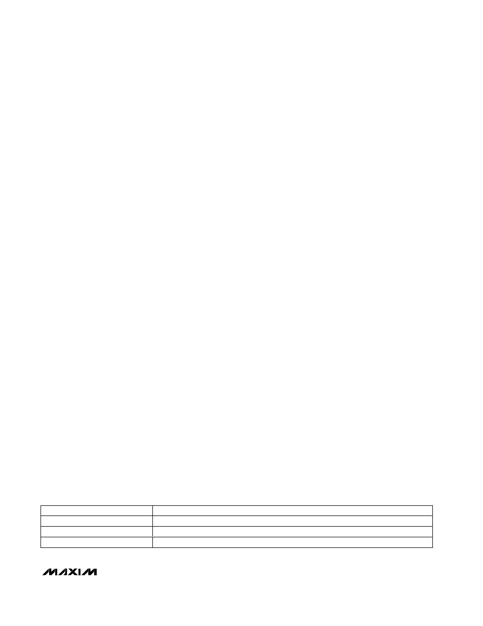
Battery Full (
CHG
)
CHG is low when the MAX1874 is charging in either the
prequal or full-charging state. CHG then goes high
when the charging current falls below a percentage of
the set fast-charge current (Table 2) and the charger is
in voltage mode (V
BATT
near 4.2V). The CHG current
threshold is a function of the charger mode. When
charging from a DC source, CHG goes high when
I
BATT
falls to 12.5% of the current set by V
DCI
and the
charger is in voltage mode (V
BATT
near 4.2V). When
charging from a USB source with USEL high, CHG
goes high when I
BATT
falls to 125mA and the charger is
in voltage mode. If the MAX1874 is charging from a
USB source with USEL low, CHG goes high when the
charger enters voltage mode.
Package Thermal Limiting
On-chip thermal limiting in the MAX1874 simplifies PC
board layout and allows charging rates to be automati-
cally optimized without constraints imposed by worst-
case minimum battery voltage, maximum input voltage,
and maximum ambient temperature. When the
MAX1874 thermal limit is reached, the charger does not
shut down but simply reduces charging current. This
allows the board design to be optimized for compact
size and typical thermal conditions. The MAX1874
reduces charging current to keep its die temperature
below +105°C.
MAX1874
Dual-Input, USB/AC Adapter, 1-Cell
Li+ Charger with OVP and Thermal Regulation
______________________________________________________________________________________
11
CHARGING SOURCE
CHARGE CURRENT THRESHOLD FOR
CHG GOING HIGH
DCLV Charging
12.5% of Charge Current Set by DCI and Charger in Voltage Mode
USB Charging 500mA (USEL high)
125mA and Charger in Voltage Mode
USB Charging 100mA (USEL low)
Charger in Voltage Mode
Table 2. CHG Battery Full Indication
Note:
CHG
does not go high when charge current is reduced by the thermal regulation loop.