Pin description – Rainbow Electronics MAX767 User Manual
Page 5
MAX767
5V-to-3.3V, Synchronous, Step-Down
Power-Supply Controller
_______________________________________________________________________________________
5
______________________________________________________________Pin Description
16
NAME
FUNCTION
1
CS
Current-sense input: +100mV = nominal current-limit level referred to FB.
2
SS
Soft-start input. Ramp time to full current limit is 1ms/nF of capacitance to GND.
3
ON
ON/O
—
F
—
F
–
control input to disable the PWM. Tie directly to V
CC
for automatic start-up.
PIN
DL
Gate-drive output for the low-side synchronous rectifier MOSFET
4–7, 11
GND
Low-current analog ground. Feedback reference point for the output.
8
REF
3.3V internal reference output. Bypass to GND with 0.22µF minimum capacitor.
9
SYNC
Oscillator control/synchronization input. Connect to V
CC
or GND for 200kHz; connect to REF for
300kHz. For external clock synchronization in the 240kHz to 350kHz range, a high-to-low transition
causes a new cycle to start.
10, 14, 15
V
CC
Supply voltage input: 4.5V to 5.5V
17
BST
Boost capacitor connection (0.1µF)
12
N.C.
No internal connection
13
PGND
Power ground
18
LX
Inductor connection. Can swing 2V below GND without latchup.
19
DH
Gate-drive output for the high-side MOSFET
20
FB
Feedback and current-sense input for the PWM
OUTPUT
3.3V
LX
DL
GND
SS
MAX767
ON
VCC
REF
L1
BST
DH
D2
PGND
CS
FB
SHUTDOWN
ON/OFF
N1
N2
D1
SMALL-
SIGNAL
SCHOTTKY
C1
R1
C3
0.1
µF
C2
C6
0.22
µF
C5
(OPTIONAL)
SYNC
R2
10
Ω
INPUT
4.5V TO 5.5V
0.01
µF
C4
4.7
µF
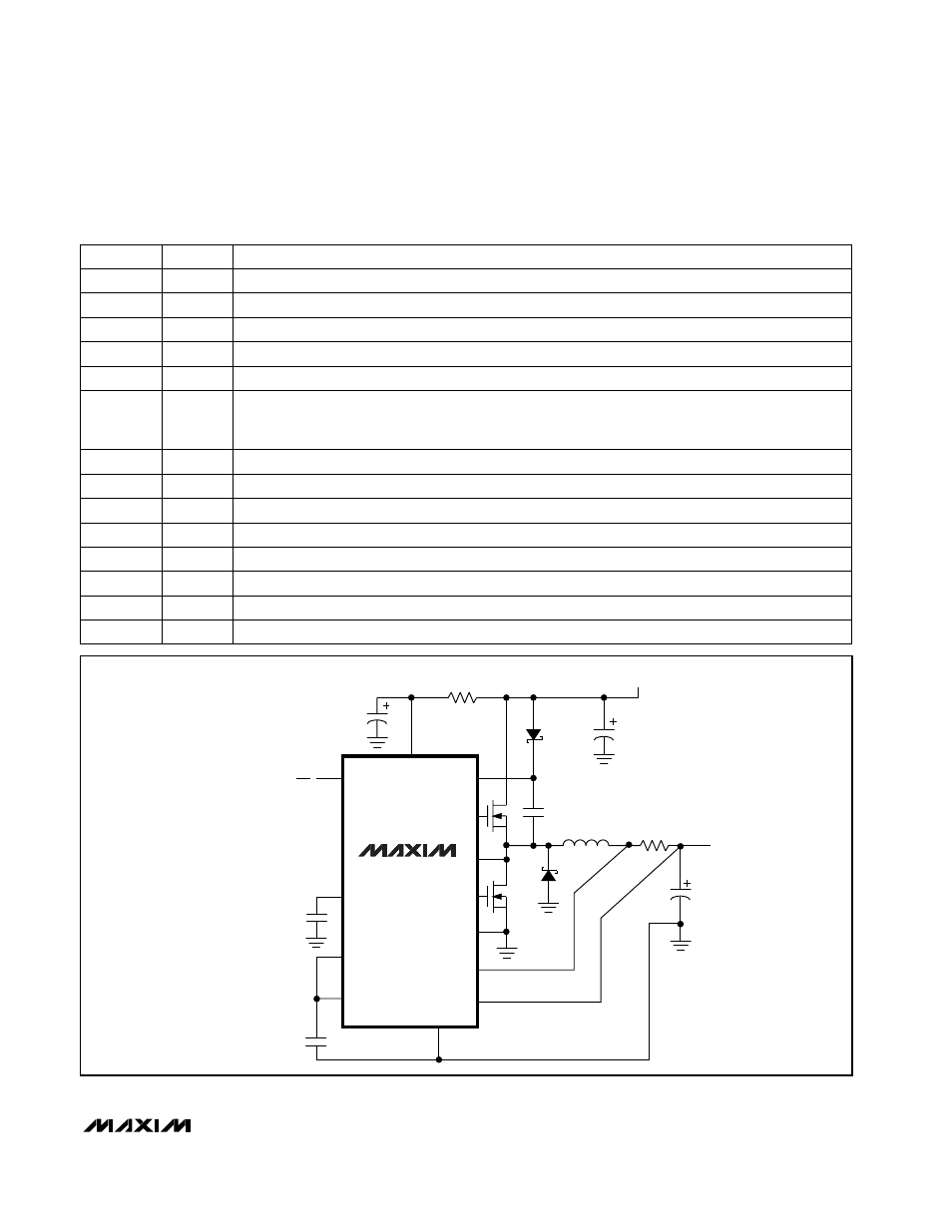
Figure 1. Standard Application Circuit