Timing characteristics – Rainbow Electronics MAX1299 User Manual
Page 5
MAX1298/MAX1299
12-Bit Serial-Output Temperature Sensors
with 5-Channel ADC
_______________________________________________________________________________________
5
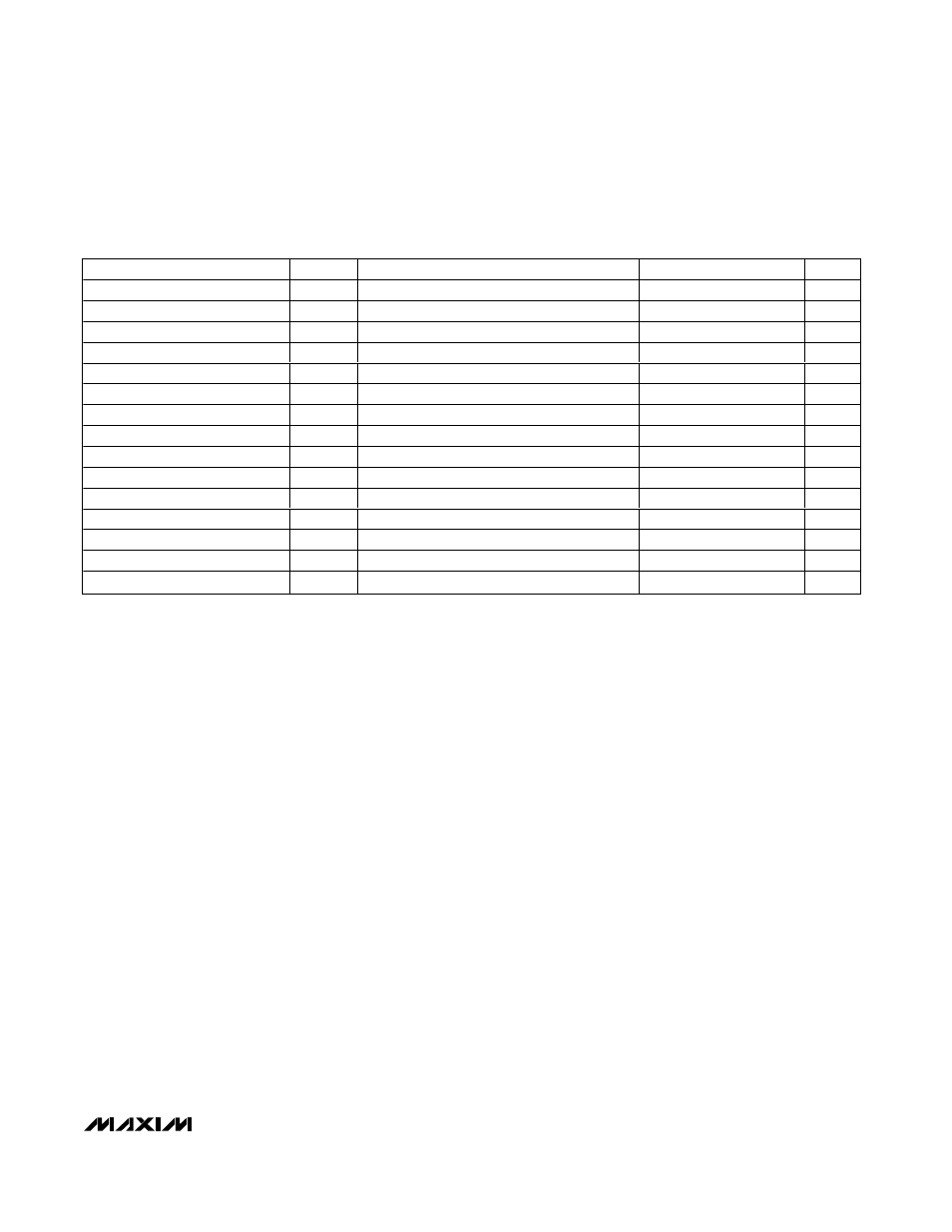
TIMING CHARACTERISTICS
(V
DD
= +4.75V to 5.25V (MAX1298), V
DD
= +2.7V to +3.6V (MAX1299), external reference, V
REF
= +2.5V (MAX1298), V
REF
= +1.2V
(MAX1299), f
SCLK
= 2.5MHz, T
A
= T
MIN
to T
MAX
, unless otherwise noted. Typical values are at T
A
= +25°C.) (Figures 4, 6)
PARAMETER
SYMBOL
CONDITIONS
MIN
TYP
MAX
UNITS
SCLK Frequency
f
SCLK
2.5
MHz
SCLK Pulse Width Low
t
CL
200
ns
SCLK Pulse Width High
t
CH
200
ns
CS Low to SCLK High
t
CSS
100
ns
SCLK High to CS Setup
t
CSH
100
ns
CS Pulse Width
t
CS
100
ns
SCLK High to CS Low Setup
t
CS0
50
ns
SCLK High to CS High Setup
t
CS1
100
ns
DIN Setup to SCLK High Time
t
DS
100
ns
DIN Hold Time
t
DH
0
ns
SCLK Fall to Output Data Valid
t
DO
R
L
= 100k
Ω, C
L
= 50pF
150
ns
CS Fall to Output Enable
t
DV
R
L
= 100k
Ω, C
L
= 50pF
150
ns
CS Rise to Output Disable
t
TR
R
L
= 100k
Ω, C
L
= 50pF
50
ns
SSTRB Rise to SCLK Rise
t
SCLK
0
ns
SCLK Fall to SSTRB Fall
t
SSTRB
200
ns
Note 1: Tested at V
DD
= +5.0V (MAX1298) and V
DD
= +3.0V (MAX1299).
Note 2: Relative accuracy is the deviation of the analog value at any code from its theoretical value after the full-scale range has
been calibrated.
Note 3: Conversion time is defined as the number of clock cycles (64 for voltage measurements, 125 for temperature measure-
ments) multiplied by the internal clock period.
Note 4: Individual analog input voltages cannot extend beyond the power-supply rails.
Note 5: Input resistance is typically 250M
Ω; 5µA limit reflects limitations in production testing.
Note 6: Specifications for full-on status assume continuous conversions. Power modes are software selected (Table 4).
Note 7: Measured at V
FS(+4.75V)
- V
FS(+5.25V)
for the MAX1298 and at V
FS(+2.7V)
- V
FS(+3.6V)
for the MAX1299.
Note 8: External load should not change during conversions for specified accuracy.
Note 9: Excludes noise and self-heating effects. Output error for MAX129_C guaranteed by design.
Note 10: External temperature sensing over -40°C to +85°C range, device at +25°C. Guaranteed by design.