Low-voltage, step-down dc-dc converters in sot23, Detailed description, Design information – Rainbow Electronics MAX1734 User Manual
Page 6
MAX1733/MAX1734
Detailed Description
The MAX1733/MAX1734 step-down DC-DC converters
deliver over 250mA to outputs as low as 1.25V. They
use a unique proprietary current-limited control scheme
that maintains extremely low quiescent supply current
(40µA), and their high 1.2MHz (max) operating frequen-
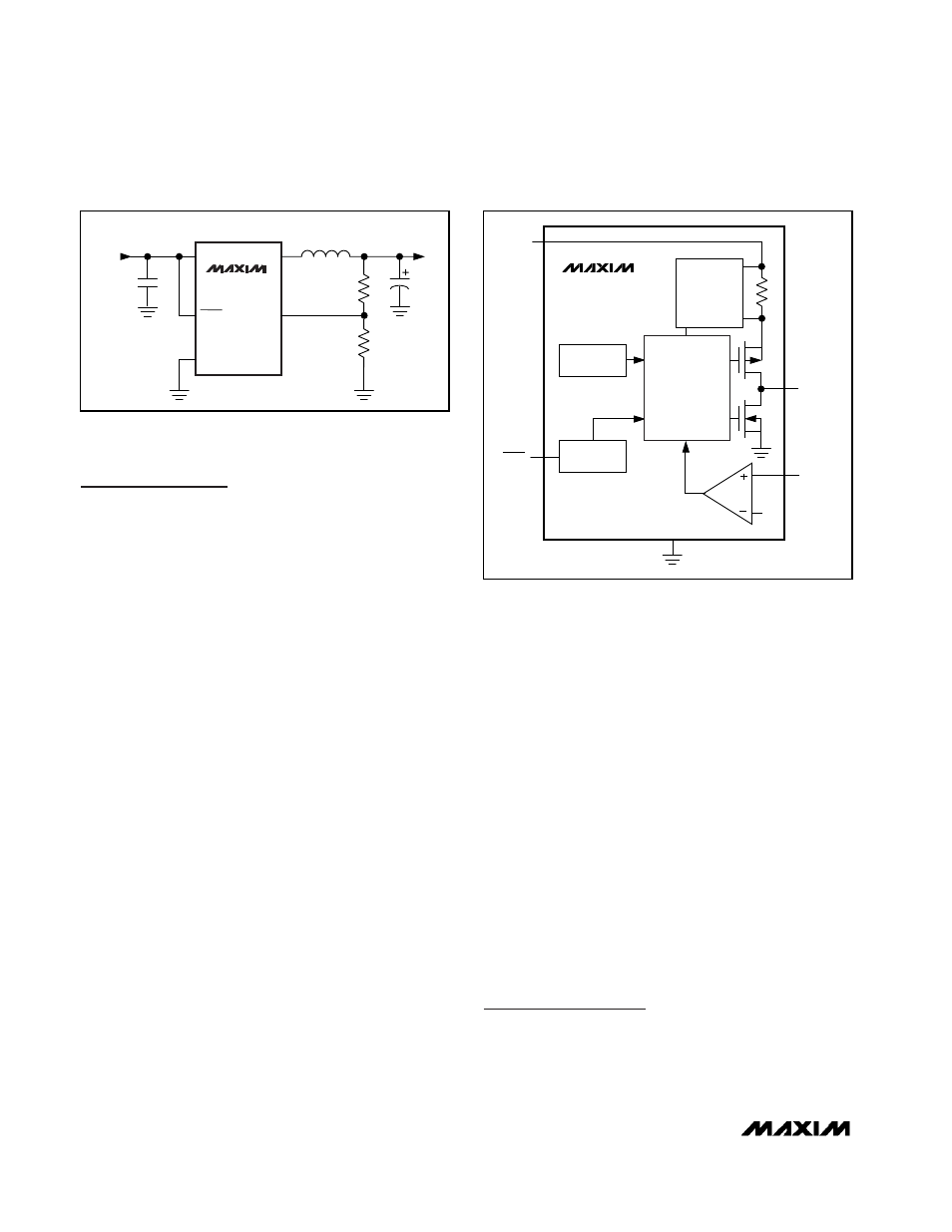
cy permits small, low-cost external components. Figure
2 is a simplified functional diagram.
Control Scheme
The MAX1733/MAX1734 use a proprietary, current-lim-
ited control scheme to ensure high-efficiency, fast tran-
sient response, and physically small external
components. This control scheme is simple: when the
output voltage is out of regulation, the error comparator
begins a switching cycle by turning on the high-side
switch. This switch remains on until the minimum on-
time of 400ns expires and the output voltage regulates
or the current-limit threshold is exceeded. Once off, the
high-side switch remains off until the minimum off-time
of 400ns expires and the output voltage falls out of reg-
ulation. During this period, the low-side synchronous
rectifier turns on and remains on until either the high-
side switch turns on again or the inductor current
approaches zero. The internal synchronous rectifier
eliminates the need for an external Schottky diode.
This control scheme allows the MAX1733/MAX1734 to
provide excellent performance throughout the entire
load-current range. When delivering light loads, the
high-side switch turns off after the minimum on-time to
reduce peak inductor current, resulting in increased
efficiency and reduced output voltage ripple. When
delivering medium and higher output currents, the
MAX1733/MAX1734 extend either the on-time or the off-
time, as necessary to maintain regulation, resulting in
nearly constant frequency operation with high efficien-
cy and low output voltage ripple.
Shutdown Mode
Connecting SHDN to GND places the MAX1733/
MAX1734 in shutdown mode and reduces supply cur-
rent to 0.01µA. In shutdown, the control circuitry, inter-
nal switching MOSFET, and synchronous rectifier turn
off and LX goes high impedance. Connect SHDN to IN
for normal operation.
Soft-Start
The MAX1733/MAX1734 have internal soft-start circuitry
that limits current draw at startup, reducing transients on
the input source. Soft-start is particularly useful for higher
impedance input sources, such as Li+ and alkaline cells.
Soft-start is implemented by starting with the current limit
at 25% of its full current value and gradually increasing it
in 25% steps until the full current limit is reached. See
Soft-Start and Shutdown Response in the Typical
Operating Characteristics section.
Design Information
Setting the Output Voltage (MAX1733)
Select an output voltage for the MAX1733 by connect-
ing FB to a resistive divider between the output and
Low-Voltage, Step-Down DC-DC Converters
in SOT23
6
_______________________________________________________________________________________
Figure 1. MAX1733 Typical Application Circuit
FB
R1
R2
V
OUT
C1
2.2
µF
C2
22
µF
L1
10
µH
LX
IN
MAX1733
SHDN
GND
INPUT
+2.7V TO +5.5V
SHDN
CONTROL
LOGIC
P
N
V
REF
OUT (FB)
LX
IN
GND
( ) ARE FOR MAX1733 ONLY.
CURRENT
LIMIT
SHUTDOWN
CONTROL
DIGITAL
SOFT-START
MAX1733
MAX1734
Figure 2. Simplified Functional Diagram