Rainbow Electronics MAX837 User Manual
Page 2
MAX836/MAX837
4-Pin Micropower Voltage Monitors
2
_______________________________________________________________________________________
ABSOLUTE MAXIMUM RATINGS
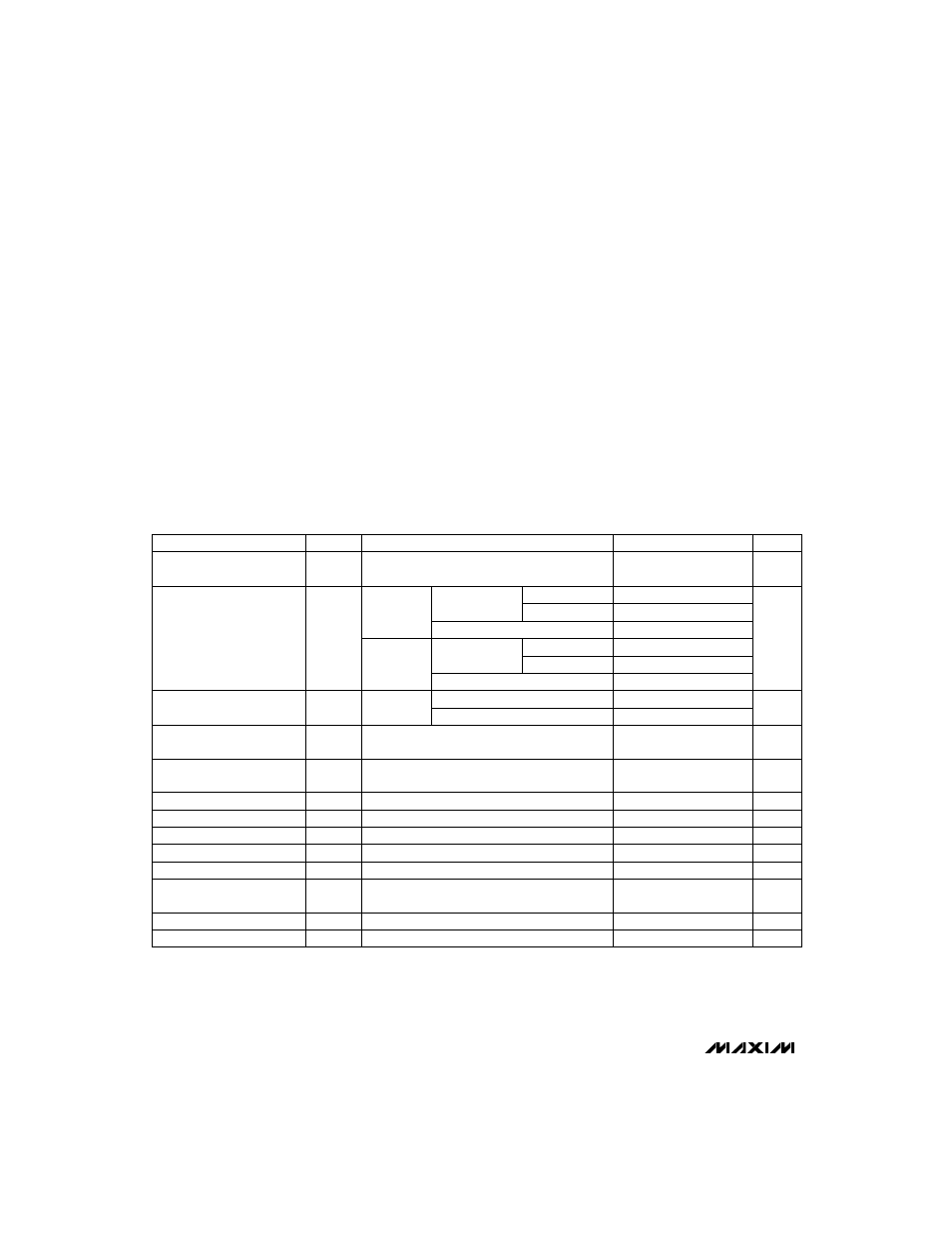
ELECTRICAL CHARACTERISTICS
(V
CC
= +2.5V to +11.0V, T
A
= T
MIN
to T
MAX
, unless otherwise noted. Typical values are at T
A
= +25°C.)
Stresses beyond those listed under “Absolute Maximum Ratings” may cause permanent damage to the device. These are stress ratings only, and functional
operation of the device at these or any other conditions beyond those indicated in the operational sections of the specifications is not implied. Exposure to
absolute maximum rating conditions for extended periods may affect device reliability.
V
CC
, OUT to GND (MAX836) ....................................-0.3V to 12V
IN, OUT to GND (MAX837).........................-0.3V to (V
CC
+ 0.3V)
Input Current
V
CC
.................................................................................20mA
IN.....................................................................................10mA
Output Current, OUT...........................................................20mA
Rate of Rise, V
CC
............................................................100V/µs
Continuous Power Dissipation
SOT143 (derate 4mW/°C above +70°C) ......................320mW
Operating Temperature Range ...........................-40°C to +85°C
Storage Temperature Range .............................-65°C to +150°C
Lead Temperature (soldering, 10sec) .............................+300°C
V
0.4
V
OL
Output Voltage Low
V
V
CC
- 0.5
V
OH
Output Voltage High
µA
±1
I
LOUT
Output Leakage Current
(Note 4)
ns
680
t
FT
OUT Fall Time
ns
260
t
RT
OUT Rise Time
µs
35
Glitch Immunity
µs
80
t
PL
Propagation Delay
V
2.5
11
V
CC
Operating Voltage Range
(Note 1)
±3
±12
nA
I
IN
IN Leakage Current (Note 3)
V
V
CC
- 1
V
IN
IN Operating Voltage Range
(Note 1)
mV
6
V
HYST
Trip Threshold Voltage
Hysteresis
V
1.185
1.204
1.215
V
TH
Trip Threshold Voltage
1.169
1.204
1.231
UNITS
MIN
TYP
MAX
SYMBOL
PARAMETER
V
CC
= 3.6V
10
V
IN
falling
T
A
= T
MIN
to T
MAX
V
IN
< V
THMIN,
I
SINK
= 500µA
V
IN
> V
THMAX
, I
SOURCE
= 500µA (MAX837 only)
V
IN
> V
THMAX
(MAX836 only)
V
IN
= V
TH
V
CC
= 5.0V, no load (MAX836 pull-up = 10k
Ω
)
V
CC
= 5.0V, no load (MAX837 only)
V
CC
= 5V, IN = low to high
V
CC
= 5.0V, 100mV overdrive
T
A
= +25°C
V
CC
= 5.0V, 50mV overdrive
CONDITIONS
T
A
= +25°C
µ
A
3.5
6.5
Supply Current (Note 2)
15
V
IN
= 1.16V,
OUT = low
I
CC
V
CC
= full operating range
2.0
5.0
T
A
= +25°C
V
CC
= 3.6V
8.0
T
A
= T
MIN
to T
MAX
13
V
IN
= 1.25V,
OUT = high
V
CC
= full operating range
T
A
= 0°C to +70°C
Note 1:
The voltage-detector output remains in the direct state for V
CC
down to 1.2V when V
IN
≤
V
CC
/ 2.
Note 2:
Supply current has a monotonic dependence on V
CC
(see
Typical Operating Characteristics
).
Note 3:
IN leakage current has a monotonic dependence on V
CC
(see
Typical Operating Characteristics
).
Note 4:
The MAX836 open-drain output can be pulled up to a voltage greater than V
CC
, but may not exceed 11V.