Rainbow Electronics MAX1524 User Manual
Page 8
MAX1522/MAX1523/MAX1524
Simple SOT23 Boost Controllers
8
_______________________________________________________________________________________
Inductor Selection
For CCM, the ideal inductor value is given by:
If L
IDEAL
is not a standard value, choose the next-clos-
est value, either higher or lower. Nominal values within
50% are acceptable. Values lower than ideal will have
slightly higher peak inductor current; values greater
than ideal will have slightly lower peak inductor current.
Due to the MAX1522/MAX1523/MAX1524s’ high switch-
ing frequencies, inductors with a ferrite core or equiva-
lent are recommended. Powdered iron cores are
not
recommended due to their high losses at frequencies
over 50kHz.
The saturation rating of the selected inductor should
meet or exceed the calculated value for I
PEAK
,
although most coil types can be operated up to 20%
over their saturation rating without difficulty. In addition
to the saturation criteria, the inductor should have as
low a series resistance as possible. The power loss in
the inductor resistance is approximately given by:
Output Capacitor Selection
In CCM, to provide stable operation and to control out-
put sag to less than 0.5%, the output bulk capacitance
should be greater than:
To properly control peak inductor current during the
3.2ms soft-start, the output bulk capacitance should be
less than:
where t
SS
= 3.2ms.
Because the MAX1522/MAX1523/MAX1524 are volt-
age-mode devices (and therefore do not require an
expensive current-sense resistor), cycle-to-cycle stabil-
ity is obtained from the output capacitor’s equivalent
series resistance (ESR). Choose an output capacitor
with actual ESR greater than:
Additionally, to control peak inductor current during soft-
start, the output capacitor’s ESR should be greater
than:
Usually, this prevents the use of ceramic capacitors in
CCM applications. Alternatives include tantalum, elec-
trolytic, and organic types such as Sanyo’s POSCAP.
The output capacitor must also be rated to withstand
the output voltage and the output ripple current, which
is equivalent to I
PEAK
. Since output ripple in boost DC-
DC designs is dominated by capacitor ESR, a capaci-
ESR
V
I
COUT
FB
PEAK
>
Ч
Ч
−
60 10
3
ESR
L
C
I
V
COUT
OUT
LOAD MAX
IN MIN
>
×
(
)
(
)
C
I
t
V
OUT MAX
LOAD MAX
SS
OUT
(
)
(
)
=
×
C
I
t
V
OUT MIN
LOAD MAX
ON
OUT
(
)
(
)
.
=
Ч
Ч
0 005
P
I
V
V
V
LR
LOAD
OUT
D
IN
RL
≅
Ч
+
Ч
(
)
2
L
V
t
I
IDEAL
IN TYP
ON TYP
PEAK
=
Ч
Ч
(
)
(
)
.
0 3
MAX1524
INPUT
3.3V
±
10%
C3
0.1
µ
F
OFF
ON
6
3
4
5
2
1
V
CC
EXT
SET
FB
SHDN
GND
C1
10
µ
F
6.3V
L1
33
µ
H
CR43-3R3
D1
CRS01
Q1
FDC633N
R1
100k
Ω
1%
OUTPUT
5V
C2
33
µ
F
10TPA33M
C
FF
100pF
R2
33.2k
Ω
1%
R3
10
Ω
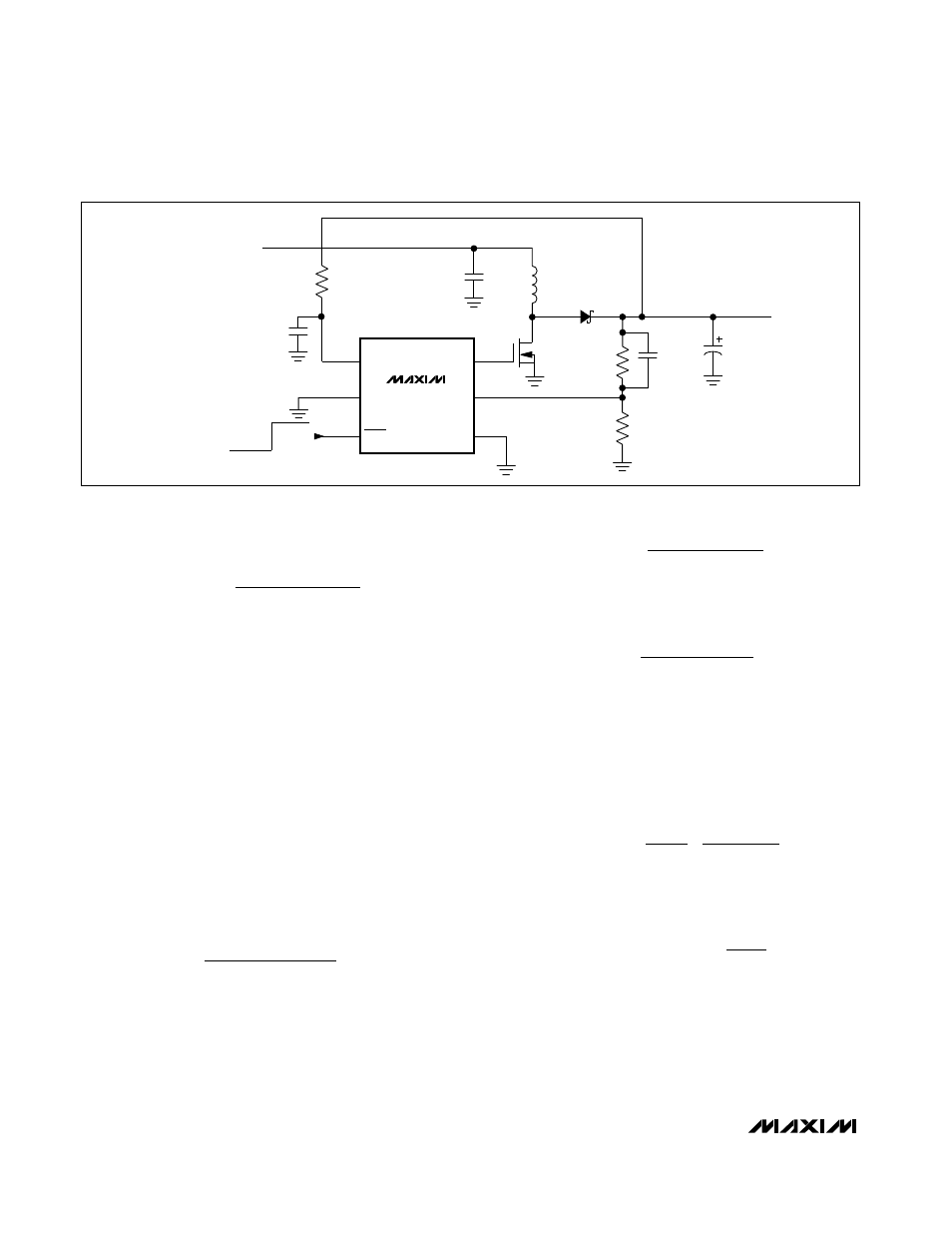
Figure 2. MAX1524 Standard Operating Circuit