Application hints, Calculating rset, Figure 1. basic current source – Rainbow Electronics LM334 User Manual
Page 5: Slew rate, Thermal effects, Shunt capacitance, Typical performance characteristics
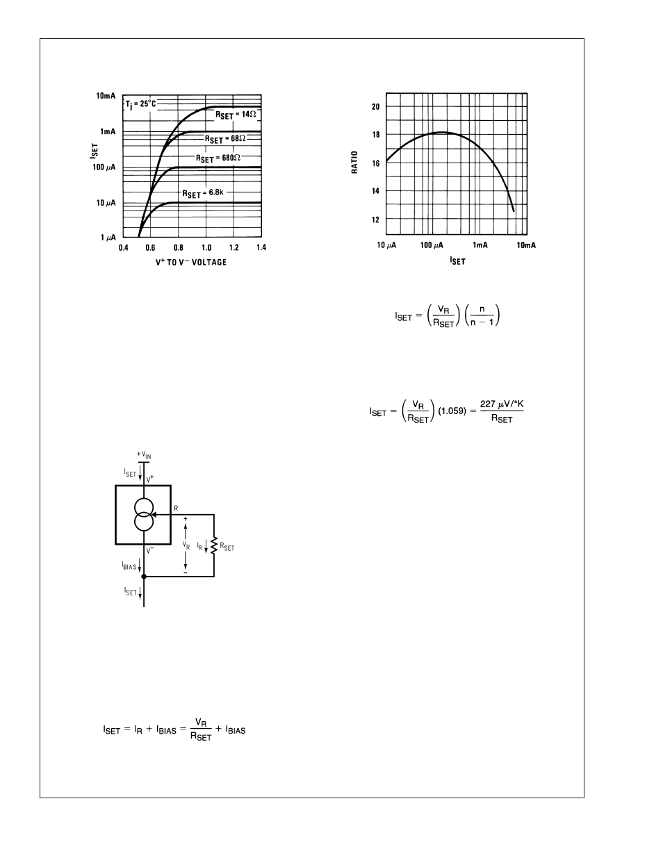
Typical Performance Characteristics
(Continued)
Turn-On Voltage
Ratio of I
SET
to I
BIAS
00569729
00569703
Application Hints
The LM134 has been designed for ease of application, but a
general discussion of design features is presented here to
familiarize the designer with device characteristics which
may not be immediately obvious. These include the effects
of slewing, power dissipation, capacitance, noise, and con-
tact resistance.
CALCULATING R
SET
The total current through the LM134 (I
SET
) is the sum of the
current going through the SET resistor (I
R
) and the LM134’s
bias current (I
BIAS
), as shown in Figure 1.
A graph showing the ratio of these two currents is supplied
under Ratio of I
SET
to I
BIAS
in the Typical Performance
Characteristics section. The current flowing through R
SET
is
determined by V
R
, which is approximately 214µV/˚K (64
mV/298˚K
∼ 214µV/˚K).
Since (for a given set current) I
BIAS
is simply a percentage of
I
SET
, the equation can be rewritten
where n is the ratio of I
SET
to I
BIAS
as specified in the
Electrical Characteristics Section and shown in the graph.
Since n is typically 18 for 2µA
≤ I
SET
≤ 1mA, the equation can
be further simplified to
for most set currents.
SLEW RATE
At slew rates above a given threshold (see curve), the
LM134 may exhibit non-linear current shifts. The slewing
rate at which this occurs is directly proportional to I
SET
. At
I
SET
= 10µA, maximum dV/dt is 0.01V/µs; at I
SET
= 1mA, the
limit is 1V/µs. Slew rates above the limit do not harm the
LM134, or cause large currents to flow.
THERMAL EFFECTS
Internal heating can have a significant effect on current
regulation for I
SET
greater than 100µA. For example, each
1V increase across the LM134 at I
SET
= 1 mA will increase
junction temperature by
≈0.4˚C in still air. Output current
(I
SET
) has a temperature coefficient of
≈0.33%/˚C, so the
change in current due to temperature rise will be (0.4)
(0.33) = 0.132%. This is a 10:1 degradation in regulation
compared to true electrical effects. Thermal effects, there-
fore, must be taken into account when DC regulation is
critical and I
SET
exceeds 100µA. Heat sinking of the TO-46
package or the TO-92 leads can reduce this effect by more
than 3:1.
SHUNT CAPACITANCE
In certain applications, the 15 pF shunt capacitance of the
LM134 may have to be reduced, either because of loading
problems or because it limits the AC output impedance of the
current source. This can be easily accomplished by buffering
the LM134 with an FET as shown in the applications. This
can reduce capacitance to less than 3 pF and improve
00569727
FIGURE 1. Basic Current Source
LM134/LM234/LM334
www.national.com
5