Figure 4, Schematic diagram, Typical applications – Rainbow Electronics LM334 User Manual
Page 11
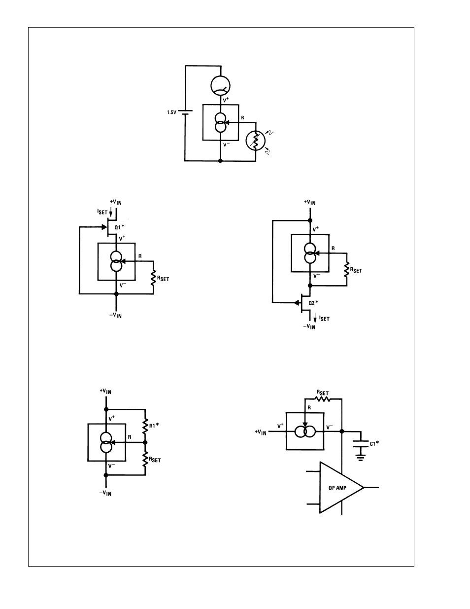
Typical Applications
(Continued)
Buffer for Photoconductive Cell
00569751
Generating Negative Output Impedance
00569723
*Z
OUT
≈ −16 • R1 (R1/V
IN
must not exceed I
SET
)
In-Line Current Limiter
00569709
*Use minimum value required to ensure stability of protected device. This
minimizes inrush current to a direct short.
Schematic Diagram
FET Cascoding for Low Capacitance and/or Ultra High Output Impedance
00569721
*Select Q1 or Q2 to ensure at least 1V across the LM134. V
p
(1 −
I
SET
/I
DSS
)
≥ 1.2V.
00569722
FIGURE 4.
LM134/LM234/LM334
www.national.com
11
See also other documents in the category Rainbow Electronics Sensors:
- MAX5151 (16 pages)
- MAXQ3108 (64 pages)
- MAX5661 (39 pages)
- MAX6691 (7 pages)
- MAX5362 (12 pages)
- ADC10158 (26 pages)
- MAX8922L (14 pages)
- MAX8596Z (8 pages)
- MAX7491 (18 pages)
- MAX15040 (15 pages)
- MAX5177 (16 pages)
- ADC08138 (22 pages)
- MAX5961 (42 pages)
- T89C51RD2 (86 pages)
- MAX16055 (9 pages)
- MAX6659 (17 pages)
- ADC0820 (20 pages)
- MAX6678 (19 pages)
- MAX8884Z (15 pages)
- MAX16915 (9 pages)
- MAX8620 (18 pages)
- MAX5144 (12 pages)
- MAX6670 (8 pages)
- MAX8760 (39 pages)
- W78C32C (14 pages)
- MX7533 (8 pages)
- MAX8727 (13 pages)
- MAX9053 (15 pages)
- W78C54 (16 pages)
- MAX8614B (15 pages)
- W90N740 (219 pages)
- MAX6626 (13 pages)
- ADC10738 (30 pages)
- MAX17000 (31 pages)
- MAX5051 (21 pages)
- MAXQ1004 (18 pages)
- MAX6871 (51 pages)
- MX7847 (12 pages)
- MAX6608 (6 pages)
- MAX17083 (15 pages)
- MAX6641 (17 pages)
- MAX5251 (16 pages)
- MAX6338 (8 pages)
- MAX6690 (16 pages)
- MAX8668 (18 pages)