Optical isolation – Rainbow Electronics MAX1402 User Manual
Page 37
MAX1402
+5V, 18-Bit, Low-Power, Multichannel,
Oversampling (Sigma-Delta) ADC
______________________________________________________________________________________
37
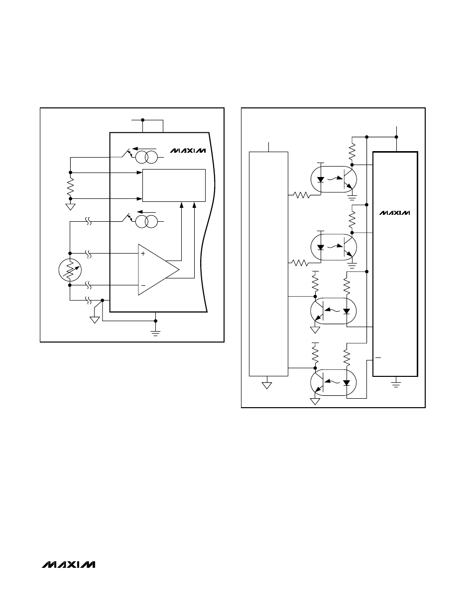
Figure 20. 4-Wire RTD Application
V+
200
µ
A
+5V
V
DD
OUT2
REFIN+
AIN1
AIN2
AGND
DGND
PGA
MODULATOR
A = 1 TO 128
200
µ
A
RTD
R
REF
REFIN-
OUT1
MAX1402
board is dedicated to ground planes while signals are
placed on the solder side.
Good decoupling is important when using high-resolu-
tion ADCs. Decouple all analog supplies with 10µF tan-
talum capacitors in parallel with 0.1µF HF ceramic
capacitors to AGND. Place these components as close
to the device as possible to achieve the best decou-
pling.
See the MAX1402 evaluation kit manual for the recom-
mended layout. The evaluation board package includes
a fully assembled and tested evaluation board.
Optical Isolation
For applications that require an optically isolated
interface, refer to Figure 21. With 6N136-type optocou-
plers, maximum clock speed is 4MHz. Maximum clock
speed is limited by the degree of mismatch between
the individual optocouplers. Faster optocouplers allow
faster signaling at a higher cost.
2k
2k
6N136
6N136
6N136
6N136
MOSI
470
Ω
SCK
MISO
INT
+V
DD
V
CC
V
CC
470
Ω
470
Ω
470
Ω
V
CC
V
CC
INT
ISO
+5V
DOUT
SCLK
DIN
2k
2k
MAX1402
Figure 21. Optically Isolated Interface