Typical operating characteristics (continued), Pin description – Rainbow Electronics MAX1730 User Manual
Page 5
MAX1730
50mA Regulated Step-Down Charge Pump
for 1.8V or 1.9V Logic
_______________________________________________________________________________________
5
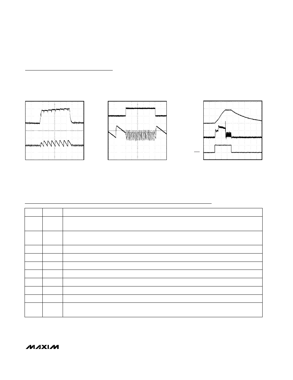
LINE-TRANSIENT RESPONSE
MAX1730 TOC07
10
µs/div
4V
V
IN
3V
V
OUT
AC-COUPLED
50mV/div
LOAD-TRANSIENT RESPONSE
MAX1730 TOC08
10
µs/div
50mA
I
OUT
5mA
V
OUT
AC-COUPLED
20mV/div
STARTUP AND SHUTDOWN RESPONSE
MAX1730 TOC09
100
µs/div
I
IN
50mA/div
V
SHDN
5V/div
V
O
1V/div
R
L
= 72
Ω
Typical Operating Characteristics (continued)
(V
IN
= +3.6V, FB = GND, SHDN = IN, C
IN
= 1µF, C1 = C2 = 0.22µF, C
OUT
= 4.7µF, T
A
= +25°C, unless otherwise noted.)
Pin Description
Output. Bypass to GND with a 4.7µF or greater capacitor.
OUT
9
Input Supply. Connect to a +2.7V to +5.5V supply. Bypass to GND with a 1µF ceramic capacitor as close to
the IC as possible.
IN
10
Ground
GND
5
Power Ground
PGND
6
C2 Flying Capacitor Negative Connection
C2N
7
C2 Flying Capacitor Positive Connection
C2P
8
C1 Flying Capacitor Negative Connection
C1N
4
C1 Flying Capacitor Positive Connection
C1P
3
PIN
Active-Low Shutdown Input. Connect to logic control or to IN for normal operation. OUT disconnects from the
input in shutdown and goes to high impedance.
SHDN
2
Feedback Input. Connect FB to GND for a 1.8V output. Connect FB to IN for a 1.9V output. Do not leave FB
unconnected.
FB
1
FUNCTION
NAME