0 functional description, Lm76 – Rainbow Electronics LM76 User Manual
Page 7
1.0 Functional Description
(Continued)
“True”:
Temperature above a T
HIGH
or T_CRIT is “true” for
those respective bits. A “true” for T
LOW
is temperature below
T
LOW
.
“False”:
Assuming temperature has previously crossed
above T
HIGH
or T_CRIT, then the temperature must drop
below the points corresponding T
HYST
(T
HIGH
− T
HYST
or
T_CRIT − T
HYST
) in order for the condition to be false. For
T
LOW
, assuming temperature has previously crossed below
T
LOW
, a “false” occurs when temperature goes above T
LOW
+ T
HYST
.
The Status bits are not affected by reads or any other
actions, and always represent the state of temperature vs.
setpoints.
1.1.2 HARDWIRE OUTPUTS
The T_CRIT_A hardwire output mirrors the T_CRIT_A flag,
when the flag is true, the T_CRIT_A output is asserted at all
times regardless of mode. Reading the LM76 has no effect
on the T_CRIT_A output, although the internal conversion is
restarted.
The behavior of the INT hardwire output is as follows:
Comparator Interrupt Mode (Default):
User reading part
resets output until next measurement completes. If condition
is still true, output is set again at end of next conversion
cycle. For example, if a user never reads the part, and
temperature goes below T
LOW
then INT becomes active. It
would stay that way until temperature goes above T
LOW
+
T
HYST
. However if the user reads the part, the output would
be reset. At the end of the next conversion cycle, if the
condition is true, it is set again. If not, it remains reset.
Event Interrupt Mode:
User reading part resets output
until next condition
″
event
″
occurs (in other words, output is
only set once for a true condition, if reset by a read, it
remains reset until the next triggering threshold has been
crossed). Conversely, if a user never read the part, the
output would stay set indefinitely after the first event that set
the output. An “event” for Event Interrupt Mode is defined as:
1.
Transitioning upward across a setpoint, or
2.
Transitioning downward across a setpoint’s correspond-
ing hysteresis (after having exceeded that setpoint).
For example, if a user never read the part, and temperature
went below T
LOW
then INT would become active. It would
stay that way forever if a user never read the part.
However if the user read the part, the output would be reset.
Even if the condition is true, it will remain reset. The tem-
perature must cross above T
LOW
+ T
HYST
to set the output
again.
In either mode, reading any register in the LM76 restarts the
conversion. This allows a designer to know exactly when the
LM76 begins a comparison. This prevents unnecessary In-
terrupts just after reprogramming setpoints. Typically, sys-
tem Interrupt inputs are masked prior to reprogramming trip
points. By doing a read just after resetting trip points, but
prior to unmasking, unexpected Interrupts are prevented.
Avoid programming setpoints so close that their hysteresis
values overlap. An example would be that with a T
HYST
value
of 2˚C then setting T
HIGH
and T
LOW
to within 4˚C of each
other will violate this restriction. To be more specific, with
T
HYST
set to 2˚C assume T
HIGH
set to 64˚C. If T
LOW
is set
equal to, or higher than 60˚C this restriction is violated.
1.2 DEFAULT SETTINGS
The LM76 always powers up in a known state. LM76 power
up default conditions are:
1.
Comparator Interrupt Mode
2.
T
LOW
set to 10˚C
3.
T
HIGH
set to 64˚C
4.
T_CRIT set to 80˚C
5.
T
HYST
set to 2˚C
6.
INT and T_CRIT_A active low
7.
Pointer set to “00”; Temperature Register
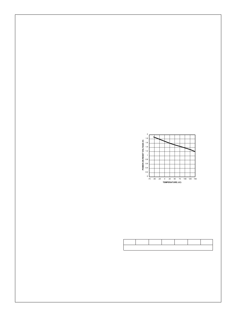
The LM76 registers will always reset to these default values
when the power supply voltage is brought up from zero volts
as the supply crosses the voltage level plotted in the follow-
ing curve. The LM76 registers will reset again when the
power supply drops below the voltage plotted in this curve.
1.3 SERIAL BUS INTERFACE
The LM76 operates as a slave on the Serial Bus, so the SCL
line is an input (no clock is generated by the LM76) and the
SDA line is a bi-directional serial data line. According to
Serial Bus specifications, the LM76 has a 7-bit slave ad-
dress. The five most significant bits of the slave address are
hard wired inside the LM76 and are “10010”. The two least
significant bits of the address are assigned to pins A1–A0,
and are set by connecting these pins to ground for a low, (0);
or to +V
S
for a high, (1).
Therefore, the complete slave address is:
1
0
0
1
0
A1
A0
MSB
LSB
Average Power on Reset Voltage
vs Temperature
DS101015-18
LM76
www.national.com
7