Logic electrical characteristics, Lm76 – Rainbow Electronics LM76 User Manual
Page 5
Logic Electrical Characteristics
(Continued)
DIGITAL DC CHARACTERISTICS Unless otherwise noted, these specifications apply for for +V
S
=+3.3 Vdc
±
5% for the
LM76CNM-3 and for +V
S
=+5.0 Vdc
±
10% for the LM76CHM-5. . Boldface limits apply for T
A
= T
J
= T
MIN
to T
MAX
; all other
limits T
A
= T
J
=+25˚C, unless otherwise noted.
Symbol
Parameter
Conditions
Typical
(Note 8)
Limits
(Note 9)
Units
(Limit)
V
IN(0)
SDA and SCL Logical “0” Input
Voltage
−0.3
V (min)
+V
S
x 0.3
V (max)
V
IN(HYST)
SDA and SCL Digital Input
Hysteresis
500
250
mV (min)
V
IN(1)
A0 and A1 Logical “1” Input
Voltage
2.0
V (min)
+V
S
+0.3
V (max)
V
IN(0)
A0 and A1 Logical “0” Input
Voltage
−0.3
V (min)
0.8
V (max)
I
IN(1)
Logical “1” Input Current
V
IN
= + V
S
0.005
1.0
µA (max)
I
IN(0)
Logical “0” Input Current
V
IN
= 0V
−0.005
−1.0
µA (max)
C
IN
Capacitance of All Digital Inputs
20
pF
I
OH
High Level Output Current
V
OH
= + V
S
10
µA (max)
V
OL
Low Level Output Voltage
I
OL
= 3 mA
0.4
V (max)
T_CRIT_A Output Saturation
Voltage
I
OUT
= 4.0 mA
(Note 12)
0.8
V (max)
T_CRIT_A Delay
1
Conversions
(max)
t
OF
Output Fall Time
C
L
= 400 pF
250
ns (max)
I
O
= 3 mA
SERIAL BUS DIGITAL SWITCHING CHARACTERISTICS Unless otherwise noted, these specifications apply for +V
S
=+3.3
Vdc
±
5% for the LM76CNM-3 and for +V
S
=+5.0 Vdc
±
10% for the LM76CHM-5, CL (load capacitance) on output lines = 80
pF unless otherwise specified. Boldface limits apply for T
A
= T
J
= T
MIN
to T
MAX
; all other limits T
A
= T
J
= +25˚C, unless other-
wise noted.
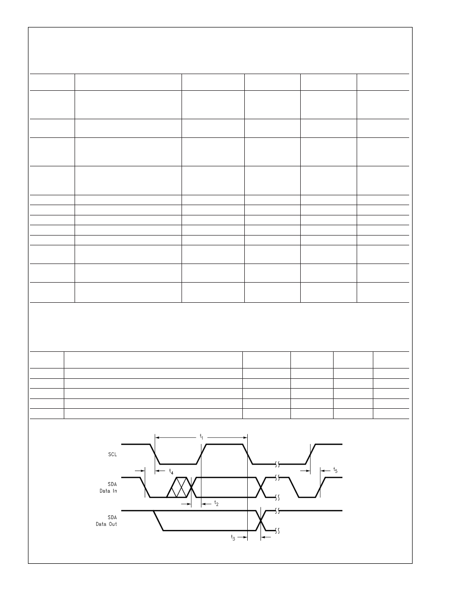
The switching characteristics of the LM76 fully meet or exceed the published specifications of the I
2
C bus. The following pa-
rameters are the timing relationship between SCL and SDA signal related to the LM76. They are not the I
2
C bus specifications.
Symbol
Parameter
Conditions
Typical
(Note 8)
Limits
(Note 9)
Units
(Limit)
t
1
SCL (Clock) Period
2.5
µs(min)
t
2
Data in Set-Up Time to SCL High
100
ns(min)
t
3
Data Out Stable after SCL Low
0
ns(min)
t
4
SDA Low Set-Up Time to SCL Low (Start Condition)
100
ns(min)
t
5
SDA High Hold Time after SCL High (Stop Condition)
100
ns(min)
DS101015-4
LM76
www.national.com
5