Table 3. external component suppliers – Rainbow Electronics MAX763A User Manual
Page 8
MAX748A/MAX763A
3.3V, Step-Down,
Current-Mode PWM DC-DC Converters
8
_______________________________________________________________________________________
Production Method
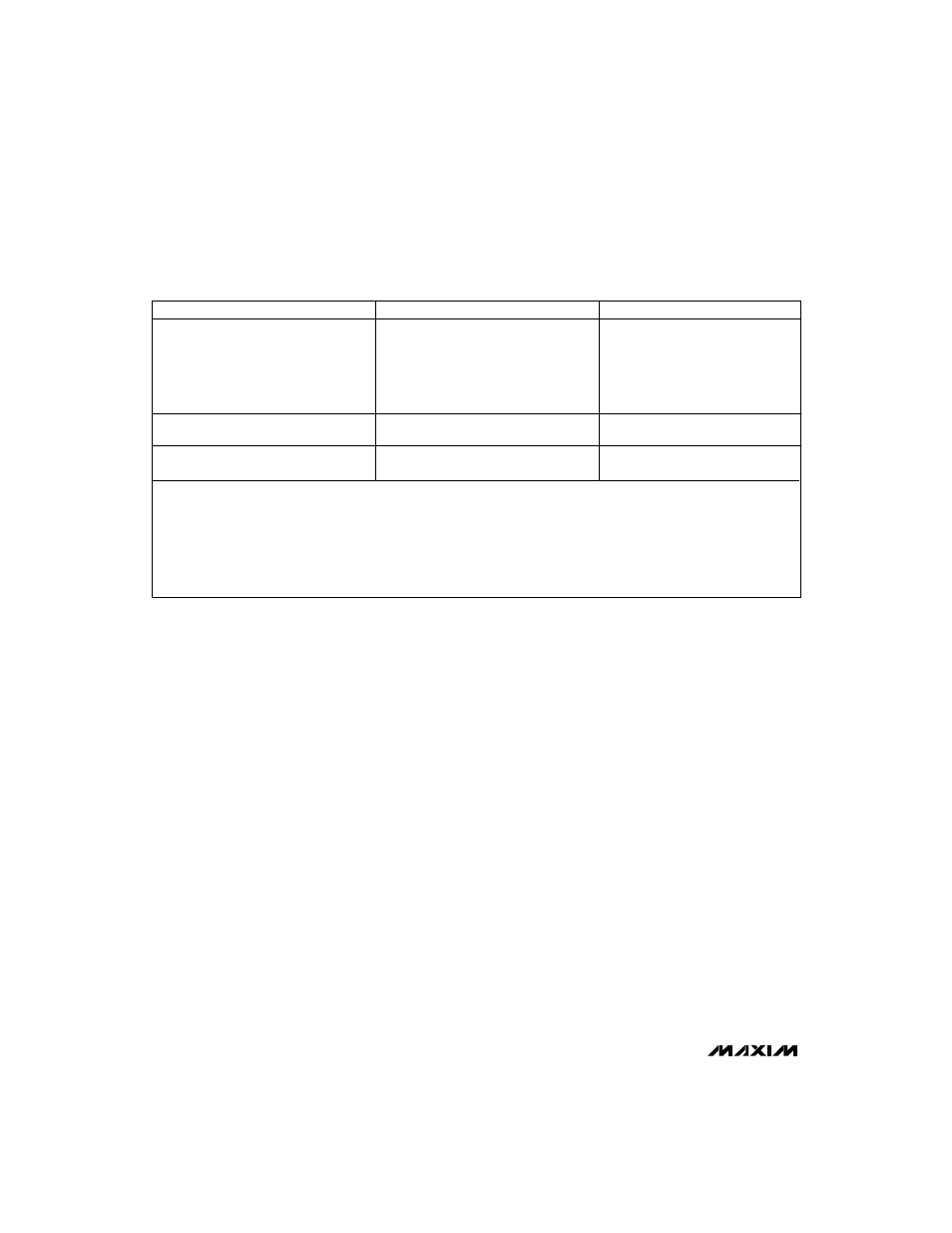
Inductors
Capacitors
Sumida
Matsuo
CD105 series
267 series
Surface Mount
Coiltronics
Sprague
CTX series
595D/293D series
Coilcraft
DT series
High Performance/
Sumida
Sanyo
Miniature Through-Hole
RCH895 series
OS-CON series (very low ESR)
Through-Hole
Renco
Nichicon
RL1284 series
PL series (low ESR)
Phone and FAX Numbers:
Coilcraft
USA:
(708) 639-6400, FAX: (708) 639-1469
Renco
USA:
(516) 586-5566, FAX: (516) 586-5562
Coiltronics
USA:
(305) 781-8900, FAX: (305) 782-4163
Sanyo
USA:
(0720) 70-1005, FAX: (0720) 70-1174
Matsuo
USA:
(714) 969-2491, FAX: (714) 960-6492
Sprague Elec. Co.
USA:
(603) 224-1961, FAX: (603) 224-1430
Japan: (06) 332-0871
Sumida
USA:
(708) 956-0666, FAX: (708) 956-0702
Nichicon
USA:
(708) 843-7500, FAX: (708) 843-2798
Japan: (03) 3607-5111, FAX: (03) 3607-5428
Table 3. External Component Suppliers
normal operation, connect
SHDN to V+. Coming out of
shutdown mode initiates an SS cycle.
Continuous-/Discontinuous-
Conduction Modes
The input voltage, output voltage, load current, and
inductor value determine whether the IC operates in
continuous or discontinuous mode. As the inductor
value or load current decreases, or the input voltage
increases, the MAX748A/MAX763A tend to operate in
discontinuous-conduction mode (DCM). In DCM, the
inductor current slope is steep enough so it decays to
zero before the end of the transistor off-time. In contin-
uous-conduction mode (CCM), the inductor current
never decays to zero, which is typically more efficient
than DCM. CCM allows the MAX748A/MAX763A to
deliver maximum load current, and is also slightly less
noisy than DCM, because it doesn’t exhibit the ringing
that occurs when the inductor current reaches zero.
Internal Reference
The +1.23V bandgap reference supplies up to 100µA
at REF. A 1000pF bypass capacitor from REF to GND
is required.
Oscillator
The MAX748A/MAX763A’s internal oscillator is guaran-
teed to operate in the 159kHz to 212.5 kHz range over
temperature for V+ = 5V. Temperature stability over the
military temperature range is about 0.04%/°C.
Undervoltage Lockout
The undervoltage lockout feature monitors the supply
voltage at V+ and allows operation to start when V+
rises above 2.95V. When V+ falls, operation continues
until the supply voltage falls below 2.7V (typ). When an
undervoltage condition is detected, control logic turns
off the output power FET and discharges the SS capac-
itor to ground. This prevents partial turn-on of the power
MOSFET and avoids excessive power dissipation. The
control logic holds the output power FET off until the
supply voltage rises above approximately 2.95V, at
which time an SS cycle begins. When the input voltage
exceeds the undervoltage lockout threshold, switching
action will occur, but the output will not be regulated
until the input voltage exceeds 3.3V (no load). The
exact input voltage required for regulation depends on
load conditions (see the Output Voltage vs. Supply
Voltage graph in the
Typical Operating Characteristics).
Shutdown Mode
The MAX748A/MAX763A are held in shutdown mode
by keeping
SHDN at ground. In shutdown mode, the
output drops to 0V and the output power FET is held in
an off state. The internal reference also turns off, which
causes the SS capacitor to discharge. Typical supply
current in shutdown mode is 0.2µA. The actual design
limit for shutdown current is much less than the 100µA
specified in the
Electrical Characteristics. However,
testing to tighter limits is prohibitive because the cur-
rent takes several seconds to settle to a final value. For