Typical operating characteristics (continued) – Rainbow Electronics MAX763A User Manual
Page 5
MAX748A/MAX763A
3.3V, Step-Down,
Current-Mode PWM DC-DC Converters
_______________________________________________________________________________________
5
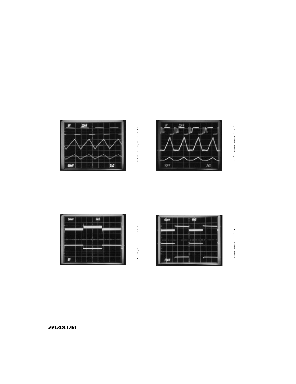
_________________________________Typical Operating Characteristics (continued)
(Circuit of Figure 3, T
A
= +25°C, V
OUT
= 3.3V, unless otherwise noted.)
SWITCHING WAVEFORMS,
CONTINUOUS CONDUCTION
2
µ
s/div
A: SWITCH VOLTAGE (LX PIN), 5V/div, 0V TO +6V
B: INDUCTOR CURRENT, 200mA/div
C: OUTPUT VOLTAGE RIPPLE, 50mV/div
V+ = 6V, IOUT = 250mA
6V
0V
400mA
0mA
A
B
B
C
SWITCHING WAVEFORMS,
DISCONTINUOUS CONDUCTION
2
µ
s/div
A: SWITCH VOLTAGE (LX PIN), 5V/div, 0V TO +6V
B: INDUCTOR CURRENT, 100mA/div
C: OUTPUT VOLTAGE RIPPLE, 50mV/div
V+ = 6V, IOUT = 75mA
6V
0V
200mA
0mA
A
C
LINE-TRANSIENT RESPONSE
5ms/div
A: VOUT, 50mV/div
B: V+, 5V/div, 7.0V TO 10.0V
IOUT = 350mA
10V
7V
0V
B
A
LOAD-TRANSIENT RESPONSE
5ms/div
A: VOUT, 50mV/div
B: IOUT, 200mA/div, 0mA TO 500mA
V+ = 6V
500mA
0mA
B
A
Note 2:
Operation beyond the specifications listed in the
Electrical Characteristics
may exceed the power dissipation ratings of
the device.
Note 3:
Wide temperature range circuit of Figure 5 using Sprague surface-mount capacitors.
Note 4:
Standby current includes all external component leakage currents. Capacitor leakage currents dominate at TA = +85°C.