Figure 1, At89c52 – Rainbow Electronics AT89S52 User Manual
Page 7
AT89C52
7
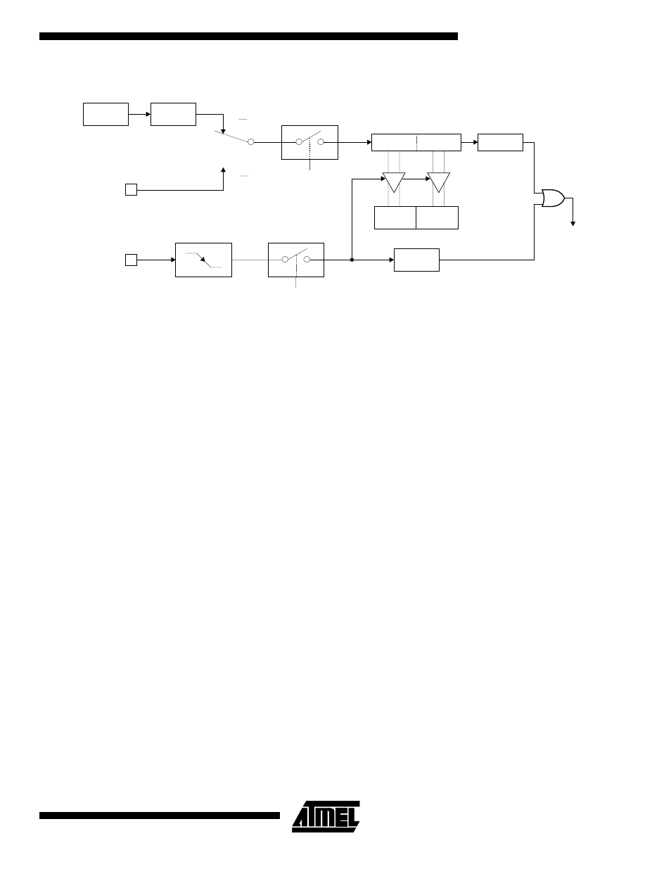
Figure 1. Timer in Capture Mode
Figure 2 shows Timer 2 automatically counting up when
DCEN = 0. In this mode, two options are selected by bit
EXEN2 in T2CON. If EXEN2 = 0, Timer 2 counts up to
0FFFFH and then sets the TF2 bit upon overflow. The
overflow also causes the timer registers to be reloaded with
the 16-bit value in RCAP2H and RCAP2L. The values in
Timer in Capture ModeRCAP2H and RCAP2L are preset
by software. If EXEN2 = 1, a 16-bit reload can be triggered
either by an overflow or by a 1-to-0 transition at external
input T2EX. This transition also sets the EXF2 bit. Both the
TF2 and EXF2 bits can generate an interrupt if enabled.
Setting the DCEN bit enables Timer 2 to count up or down,
as shown in Figure 3. In this mode, the T2EX pin controls
the direction of the count. A logic 1 at T2EX makes Timer 2
count up. The timer will overflow at 0FFFFH and set the
TF2 bit. This overflow also causes the 16-bit value in
RCAP2H and RCAP2L to be reloaded into the timer regis-
ters, TH2 and TL2, respectively.
A logic 0 at T2EX makes Timer 2 count down. The timer
underflows when TH2 and TL2 equal the values stored in
RCAP2H and RCAP2L. The underflow sets the TF2 bit and
causes 0FFFFH to be reloaded into the timer registers.
The EXF2 bit toggles whenever Timer 2 overflows or
underflows and can be used as a 17th bit of resolution. In
this operating mode, EXF2 does not flag an interrupt.
OSC
EXF2
T2EX PIN
T2 PIN
TR2
EXEN2
C/T2 = 0
C/T2 = 1
CONTROL
CAPTURE
OVERFLOW
CONTROL
TRANSITION
DETECTOR
TIMER 2
INTERRUPT
÷12
RCAP2L
RCAP2H
TH2
TL2
TF2