Integrated circuits inc, 3fe0 system flag. read only, 3fe0 system control 0. write only – Rainbow Electronics APC5800M User Manual
Page 3
INTEGRATED CIRCUITS INC.
http://www.aplusinc.com.tw
PAGE / 5 VER1.3
3
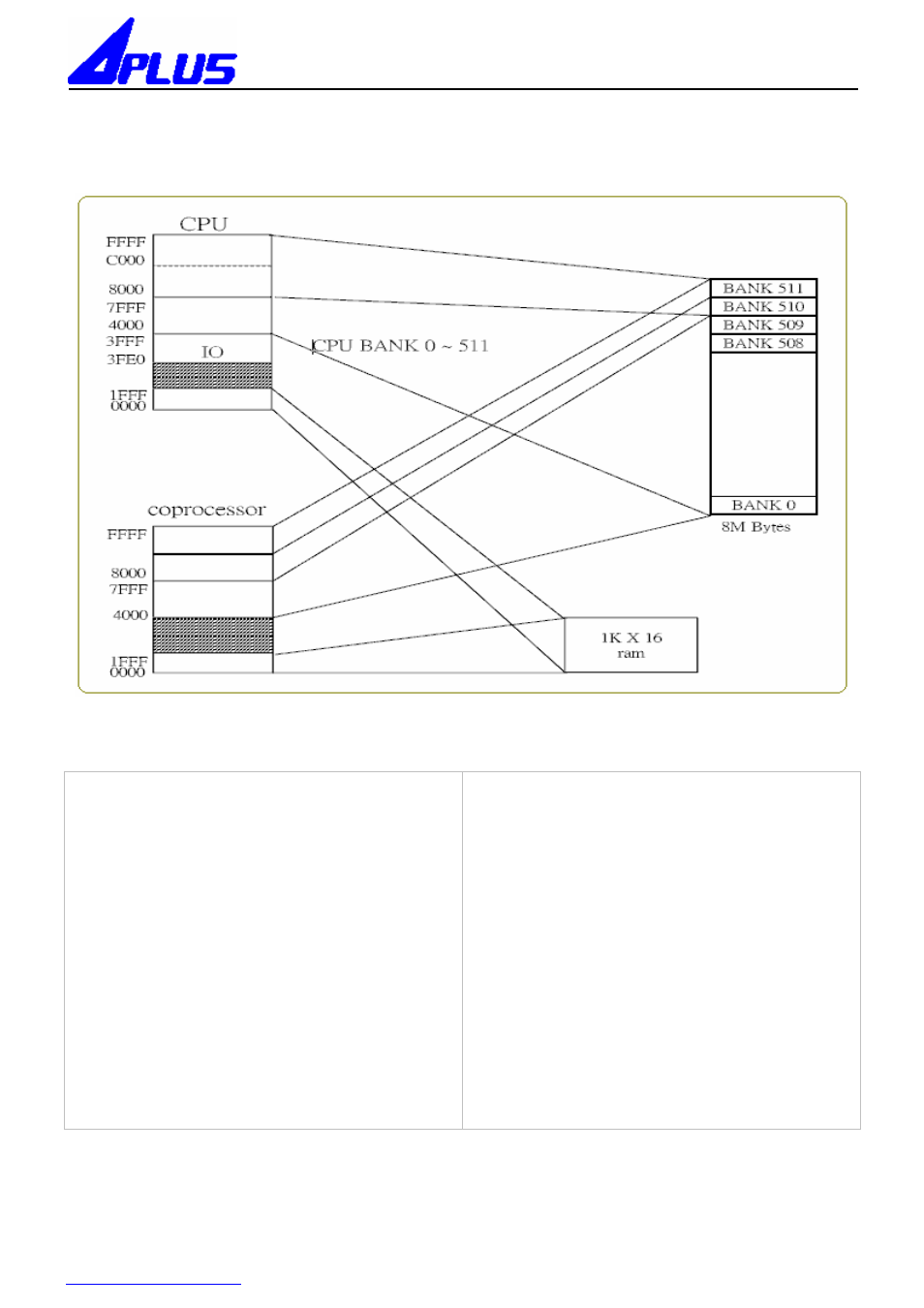
Memory Mapping
3FE0 System Flag. Read only
Bit 0: = not used
1: = no used
2: = 1 -- error in ADC
0 -- no error in ADC
3: = 1 Timer_A INT flag
Timer IRQ Timer_A INT flag
1 1 Timer_A INT
1 0 Fix_Timer INT
0 x no Timer INT
4: = 1 (not used)
5: = 1 (executed flag of Coprocessor)
6: = 1 (coprocessor’s carry)
7: = 1 (tone0 or tone1 enabled)
3FE0 System control 0. Write only
Bit 0: = must be 0.
0 --PA14 and PA15 are IO pins (default).
1: = 1-- PB9 is an EXTIRQ pin.
0-- PB9 is an IO pin (default).
2: = 1-- PB7 is EXTRAMCS.
0-- PB7 is an IO pin (default).
3: = 1-- ADC enabled; PA13 is an ADC pin.
0-ADC disabled;PA13 is an IO pin(default).
4: = not used (must be 0.)
5: = not used (must be 0.)
6: = 1-- (PWM enabled)
0 --(PWM disabled (default))
7: = 1--(DAC enabled)
0 --(DAC disabled (default))