Figure 5. temperature register format, Current measurement, Figure 6. current register formats – Rainbow Electronics DS2745 User Manual
Page 8: Table 3. current range for various rsns values
DS2745 Low-Cost I
2
C Battery Monitor
8 of 14
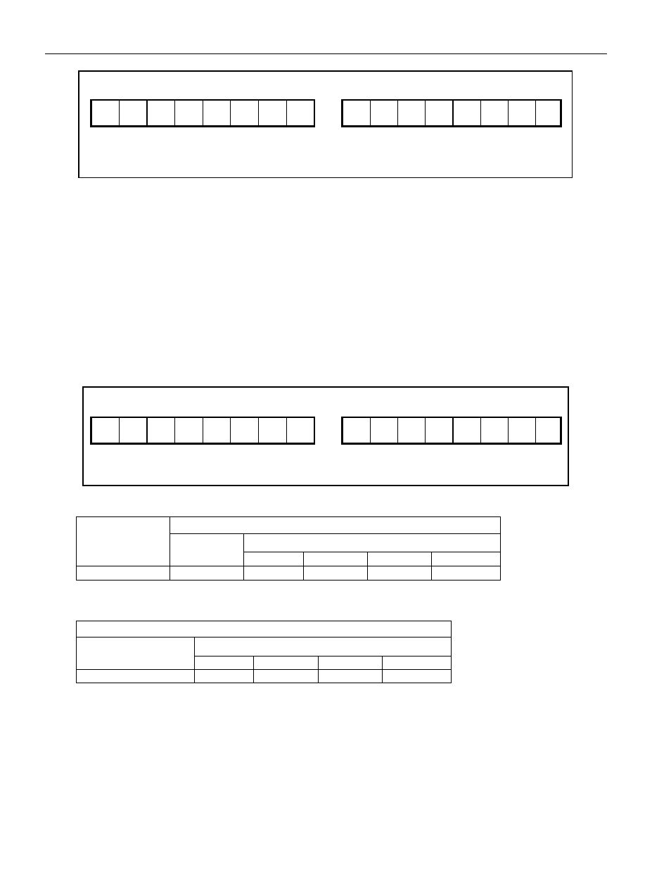
Figure 5. TEMPERATURE REGISTER FORMAT
MSB—Address
0A
LSB—Address
0B
S 2
9
2
8
2
7
2
6
2
5
2
4
2
3
2
2
2
1
2
0
X X X X X
MSb
LSb
MSb LSb
“S”: sign bit, “X”: reserved
Units: 0.125
°C
CURRENT MEASUREMENT
In the active mode of operation, the DS2745 continually measures the current flow into and out of the battery by
measuring the voltage drop across a low-value current-sense resistor, R
SNS
, connected between the SNS and VSS
pins. The voltage sense range between SNS and VSS is ±51.2mV. Note that positive current values occur when
V
SNS
is less than V
SS
, and negative current values occur when V
SNS
is greater than V
SS
. Peak signal amplitudes up
to 102mV are allowed at the input as long as the continuous or average signal level does not exceed ±51.2mV over
the conversion cycle period. The ADC samples the input differentially at with an 18.6kHz sample clock and updates
the current register at the completion of each conversion cycle. Figure 6 describes the current measurement
register format and resolution. Charge currents above the maximum register value are reported at the maximum
value (7FFFh = +51.2mV). Discharge currents below the minimum register value are reported at the minimum
value (8000h = -51.2mV).
Figure 6. CURRENT REGISTER FORMATS
MSB—Address
0E
LSB—Address
0F
S 2
14
2
13
2
12
2
11
2
10
2
9
2
8
2
7
2
6
2
5
2
4
2
3
2
2
2
1
2
0
MSb
LSb
MSb LSb
“S”: sign bit
Units:
2
0
= 1.5625
mV/Rsns
Table 2. CURRENT RESOLUTION FOR VARIOUS RSNS VALUES
CURRENT RESOLUTION (1 LSB)
R
SNS
CONVERSION
TIME
|V
SS
- V
SNS
|
20m
W 15mW 10mW 5mW
3.5s
1.5625
mV 78.13mA 104.2mA 156.3mA 312.5mA
Table 3. CURRENT RANGE FOR VARIOUS RSNS VALUES
CURRENT INPUT RANGE
R
SNS
V
SS
- V
SNS
20m
W 15mW 10mW 5mW
±51.2mV ±2.56A
±3.41A
±5.12A
±10.24A
Every 1024th conversion, the ADC measures its input offset to facilitate offset correction. Offset correction occurs
approximately once per hour. The resulting correction factor is applied to the subsequent 1023 measurements.
During the offset correction conversion, the ADC does not measure the SNS to VSS signal. A maximum error of
1/1024 in the accumulated current register (ACR) is possible, however, to reduce the error, the current
measurement just prior to the offset conversion is displayed in the current register and is substituted for the
dropped current measurement in the current accumulation process. The error due to offset correction is typically
much less than 1/1024.