Isd18b12, Pad description – Rainbow Electronics ISD18B12 User Manual
Page 5
ISD18B12
Publication Release Date: August 31, 2007
- 5 -
Revision A1
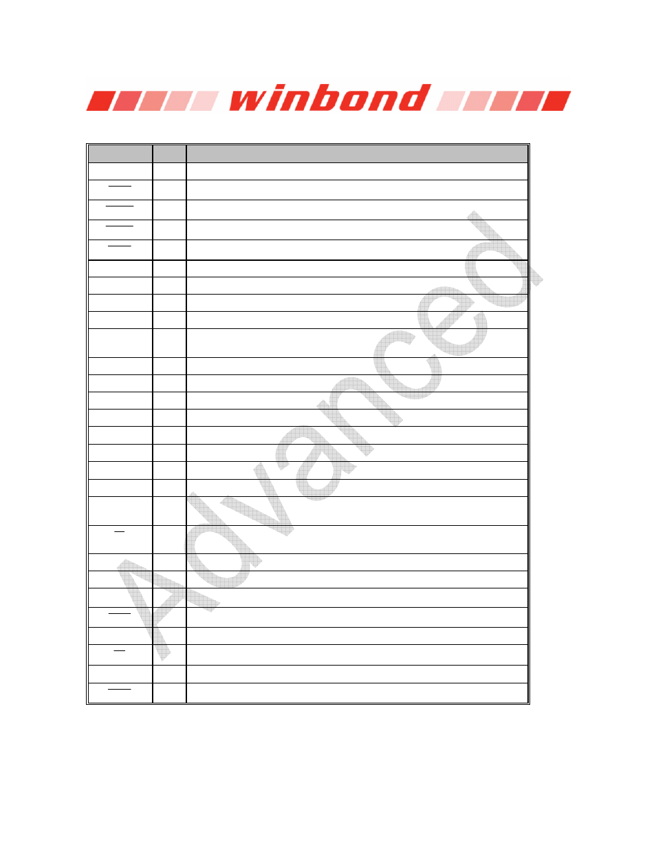
4. PAD DESCRIPTION
PAD NAME
I / O
FUNCTION
V
SSD
I
Digital Ground: Ground path for digital circuits.
RECL
I
Level-Triggered Record: Low active input, Level-hold.
PLAYE
I
Edge-Triggered Playback: Low active input, Edge-trigger,
toggle
on-off.
PLAYL
I
Level-Triggered Playback: Low active input, Level-hold.
RECE
I
Edge-Triggered Record: Low active input, Edge-trigger,
toggle
on-off.
NC
--
NC: No Connect
NC
--
NC: No Connect
NC
--
NC: No Connect
NC
--
NC: No Connect
MICIN I
Microphone Input: The MICIN transfers input signal to the on-chip
microphone amplifier.
NC
--
NC: No Connect
MICOUT O
Microphone Output: Output of the microphone amplifier.
NC
--
NC: No Connect
NC
--
NC: No Connect
SP- O
SP-: The negative signal of the differential speaker outputs.
V
SSA
I
Analog Ground: Ground path for analog circuits.
SP+ O
SP+: The positive signal of the differential speaker outputs.
V
CCA
I
Power Supply: Power supply for analog circuits.
Rosc I
Oscillator Resistor: Connect an external resistor from this pin to V
SSA
to
select the sampling frequency
FT
I
Feed-Through (FT): Low active input, Level-hold, Feed-through microphone
input to speaker outputs while in active state.
NC
--
NC: No Connect
NC
--
NC: No Connect
TryMe
I
TryMe Mode : High active input, Level-hold. A special operating mode.
LEDP
O
LED output for Playback: During playback, this output is Low.
NC
--
NC: No Connect
SE
I
Sound Effect:
Low active input, Level-hold, optional beeping sound effect.
V
CCD
I
Power Supply: Power supply for digital circuits.
LEDR
O
LED output for Recording: During recording, this output is Low.