Rainbow Electronics DS1985 User Manual
Page 4
DS1985
4 of 25
The 1-Wire CRC of the lasered ROM is generated using the polynomial X
8
+ X
5
+ X
4
+ 1. Additional
information about the Dallas Semiconductor 1-Wire Cyclic Redundancy Check is available in the Book
of DS19xx iButton Standards. The shift register acting as the CRC accumulator is initialized to 0. Then
starting with the least significant bit of the family code, one bit at a time is shifted in. After the 8th bit of
the family code has been entered, then the serial number is entered. After the 48th bit of the serial number
has been entered, the shift register contains the CRC value. Shifting in the 8 bits of CRC should return the
shift register to all 0s.
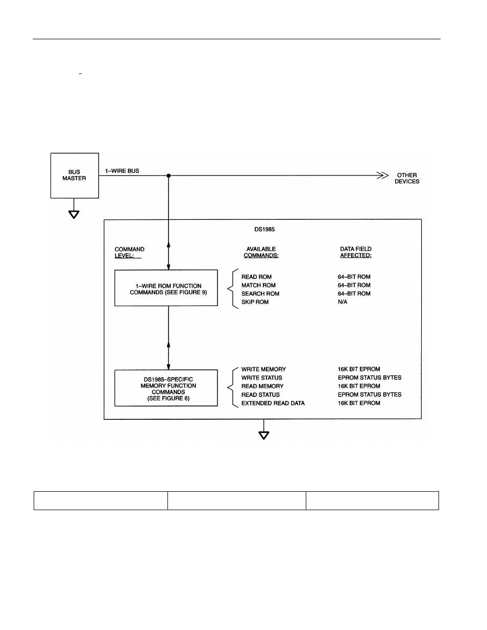
HIERARCHICAL STRUCTURE FOR 1-WIRE PROTOCOL Figure 2
64-BIT LASERED ROM Figure 3
8-Bit CRC Code
48- Bit Serial Number
8-Bit Family Code (0BH)
MSB
LSB MSB
LSB MSB
LSB
- MAX5151 (16 pages)
- MAXQ3108 (64 pages)
- MAX5661 (39 pages)
- MAX6691 (7 pages)
- MAX5362 (12 pages)
- ADC10158 (26 pages)
- MAX8922L (14 pages)
- MAX8596Z (8 pages)
- MAX7491 (18 pages)
- MAX15040 (15 pages)
- MAX5177 (16 pages)
- ADC08138 (22 pages)
- MAX5961 (42 pages)
- T89C51RD2 (86 pages)
- MAX16055 (9 pages)
- MAX6659 (17 pages)
- ADC0820 (20 pages)
- MAX6678 (19 pages)
- MAX8884Z (15 pages)
- MAX16915 (9 pages)
- MAX8620 (18 pages)
- MAX5144 (12 pages)
- MAX6670 (8 pages)
- MAX8760 (39 pages)
- W78C32C (14 pages)
- MX7533 (8 pages)
- MAX8727 (13 pages)
- MAX9053 (15 pages)
- W78C54 (16 pages)
- MAX8614B (15 pages)
- W90N740 (219 pages)
- MAX6626 (13 pages)
- ADC10738 (30 pages)
- MAX17000 (31 pages)
- MAX5051 (21 pages)
- MAXQ1004 (18 pages)
- MAX6871 (51 pages)
- MX7847 (12 pages)
- MAX6608 (6 pages)
- MAX17083 (15 pages)
- MAX6641 (17 pages)
- MAX5251 (16 pages)
- MAX6338 (8 pages)
- MAX6690 (16 pages)
- MAX8668 (18 pages)