Rainbow Electronics DS1985 User Manual
Page 20
DS1985
20 of 25
(Figure 11) should be applied for 480
µ
s, after which the bus master returns the data line to an idle high
state controlled by the pullup resistor. Note that due to the high voltage programming requirements for
any 1-Wire EPROM device, it is not possible to multidrop non-EPROM based 1-Wire devices with the
DS1985 during programming. An internal diode within the non-EPROM based 1-Wire devices will
attempt to clamp the data line at approximately 8 volts and could potentially damage these devices.
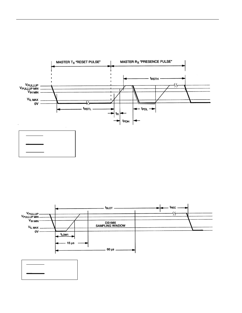
INITIALIZATION PROCEDURE “RESET AND PRESENCE PULSES” Figure 9
480
µ
s
≤
t
RSTL
<
∞
*
480
µ
s
≤
t
RSTH
<
∞
(includes recovery time)
15
µ
s
≤
t
PDH
< 60
µ
s
60
µ
s
≤
t
PDL
< 240
µ
s
∗
In order not to mask interrupt signaling by other devices on the 1-Wire bus, t
RSTL
+ t
R
should always
be less than 960
µ
s.
READ/WRITE TIMING DIAGRAM Figure 10
Write-1 Time Slot
60
µ
s
≤
t
SLOT
< 120
µ
s
1
µ
s
≤
t
LOW1
< 15
µ
s
1
µ
s
≤
t
REC
<
∞
RESISTOR
MASTER
RESISTOR
MASTER
DS1985
- MAX5151 (16 pages)
- MAXQ3108 (64 pages)
- MAX5661 (39 pages)
- MAX6691 (7 pages)
- MAX5362 (12 pages)
- ADC10158 (26 pages)
- MAX8922L (14 pages)
- MAX8596Z (8 pages)
- MAX7491 (18 pages)
- MAX15040 (15 pages)
- MAX5177 (16 pages)
- ADC08138 (22 pages)
- MAX5961 (42 pages)
- T89C51RD2 (86 pages)
- MAX16055 (9 pages)
- MAX6659 (17 pages)
- ADC0820 (20 pages)
- MAX6678 (19 pages)
- MAX8884Z (15 pages)
- MAX16915 (9 pages)
- MAX8620 (18 pages)
- MAX5144 (12 pages)
- MAX6670 (8 pages)
- MAX8760 (39 pages)
- W78C32C (14 pages)
- MX7533 (8 pages)
- MAX8727 (13 pages)
- MAX9053 (15 pages)
- W78C54 (16 pages)
- MAX8614B (15 pages)
- W90N740 (219 pages)
- MAX6626 (13 pages)
- ADC10738 (30 pages)
- MAX17000 (31 pages)
- MAX5051 (21 pages)
- MAXQ1004 (18 pages)
- MAX6871 (51 pages)
- MX7847 (12 pages)
- MAX6608 (6 pages)
- MAX17083 (15 pages)
- MAX6641 (17 pages)
- MAX5251 (16 pages)
- MAX6338 (8 pages)
- MAX6690 (16 pages)
- MAX8668 (18 pages)