Rainbow Electronics ATR0630P1 User Manual
Page 10
10
4978AS–GPS–12/07
ATR0630P1
Boot Section
C6
BOOT_MODE
DIGITAL IN
-
Leave open, internal pull down
Reset
A7
NRESET
DIGITAL IN
Low
Reset input; open drain with internal pull-up resistor
APMC/Power Management
E9
NSHDN
DIGITAL OUT
Low
Shutdown output, connect to LDO_EN (C11)
C11
LDO_EN
DIGITAL IN
-
Enable LDO18
E10 NSLEEP
DIGITAL
OUT
Low
Power-up
output
for GPS XTAL, connect to PUXTO (F4)
F4
PUXTO
DIGITAL IN
-
Power-up input for GPS XTAL
G4, H4
PURF
DIGITAL IN
-
Power-up input for GPS radio
F10
RF_ON
DIGITAL OUT
-
Power-up output for GPS radio, connect to PURF (G4, H4)
Advanced Interrupt Controller (AIC)
A11, B10
EXTINT0-1
DIGITAL IN
High/Low/
Edge
External interrupt request
USART
C10, D10
RXD1/RXD2
DIGITAL IN
-
USART receive data
C7, E6
TXD1/TXD2
DIGITAL OUT
-
USART transmit data
H6, G7
SCK1/SCK2
DIGITAL I/O
-
External synchronous serial clock
USB
C9
USB_DP
DIGITAL I/O
-
USB data (D+)
D9
USB_DM
DIGITAL I/O
-
USB data (D-)
SPI Interface
F8
SCK
DIGITAL I/O
-
SPI clock
H7
MOSI
DIGITAL I/O
-
Master out slave in
G5
MISO
DIGITAL I/O
-
Master in slave out
B6
NSS/NPCS0
DIGITAL I/O
Low
Slave select
F7, D6, D5
NPCS1/NPCS2
/NPCS3
DIGITAL OUT
Low
Slave select
PIO
A11, B[6,10],
C[6-8,10],
D[5-8,10],
E[6,7],
F[6-8],
G[5-8],
H[6,7]
P0 to P31
DIGITAL I/O
-
Programmable I/O ports
Configuration
B[6,10],
D[5,6,8],
F[6-8], H[6,7]
GPSMODE0-1
2
DIGITAL IN
-
GPS mode pins
G8
NEEPROM
DIGITAL IN
Low
Enable EEPROM support
GPS
D7 STATUSLED
DIGITAL
OUT
-
Status
LED
G7
TIMEPULSE
DIGITAL OUT
-
GPS synchronized time pulse
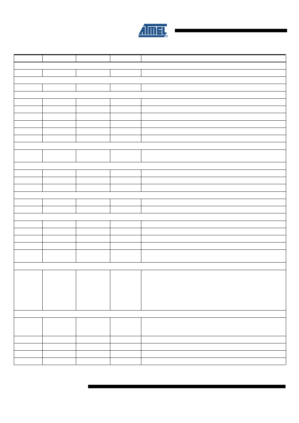
Table 3-2.
Signal Description (Continued)
Pin Number
Pin Name
Type
Active Level Pin Description/Comment