Chip information, Table 3. command byte definitions – Rainbow Electronics MAX5821 User Manual
Page 11
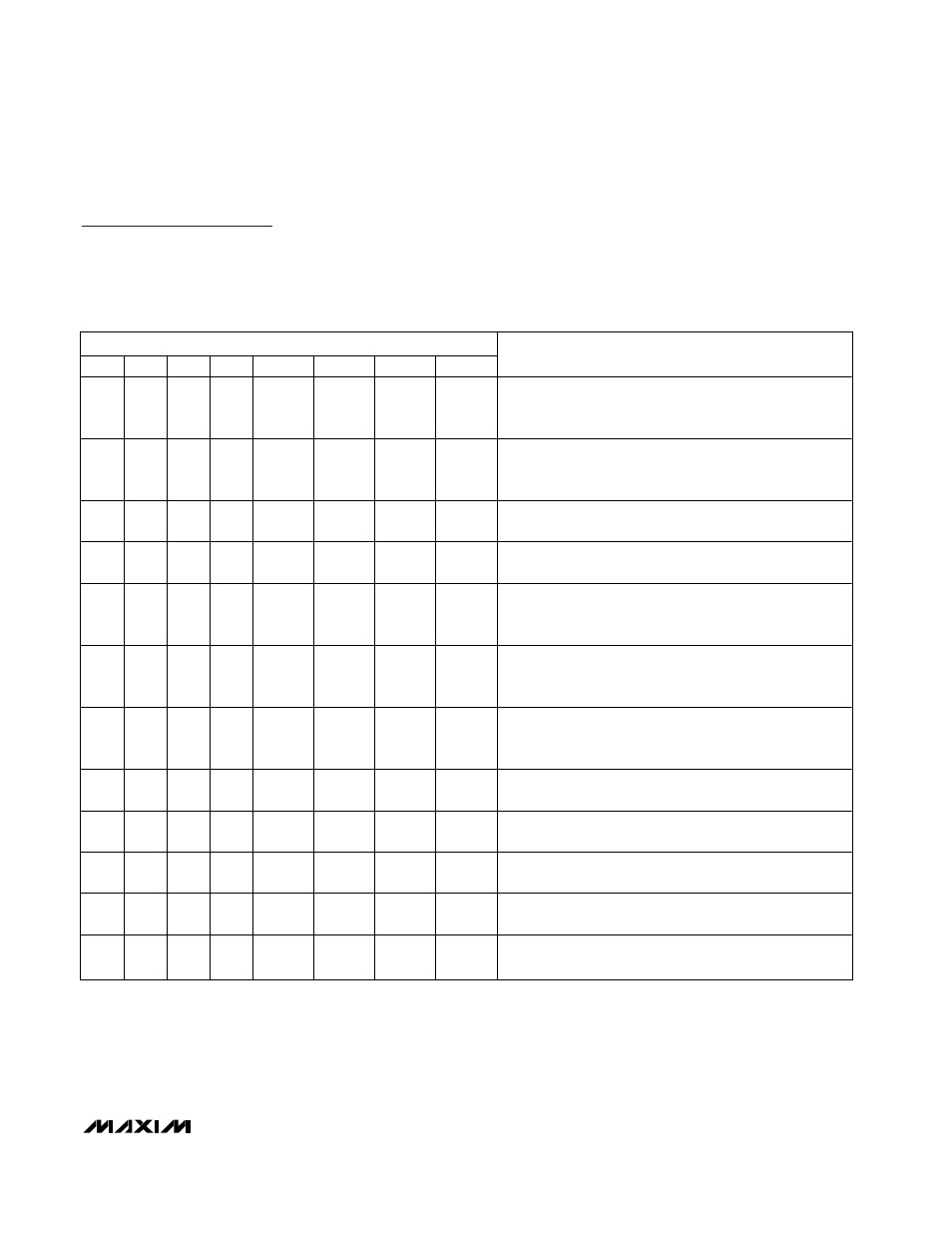
Chip Information
TRANSISTOR COUNT: 11,186
PROCESS: BiCMOS
MAX5822
Dual, 12-Bit, Low-Power, 2-Wire, Serial
Voltage-Output DAC
______________________________________________________________________________________
11
SERIAL DATA INPUT
C3
C2
C1
C0
D11
D10
D9
D8
FUNCTION
0
0
0
0
DAC
DATA
DAC
DATA
DAC
DATA
DAC
DATA
Load DAC A input and DAC registers with new data.
Contents of DAC B input registers are transferred to the
DAC register. Both outputs are updated.
0
0
0
1
DAC
DATA
DAC
DATA
DAC
DATA
DAC
DATA
Load DAC B input and DAC registers with new data.
Contents of DAC A input registers are transferred to the
DAC register. Both outputs are updated simultaneously.
0
1
0
0
DAC
DATA
DAC
DATA
DAC
DATA
DAC
DATA
Load DAC A input register with new data. DAC outputs
remain unchanged.
0
1
0
1
DAC
DATA
DAC
DATA
DAC
DATA
DAC
DATA
Load DAC B input register with new data. DAC outputs
remain unchanged.
1
0
0
0
DAC
DATA
DAC
DATA
DAC
DATA
DAC
DATA
Data in all input registers is transferred to respective DAC
registers. All DAC outputs are updated simultaneously.
New data is loaded into DAC A input register.
1
0
0
1
DAC
DATA
DAC
DATA
DAC
DATA
DAC
DATA
Data in all input registers is transferred to respective DAC
registers. All DAC outputs are updated simultaneously.
New data is loaded into DAC B input register.
1
1
0
0
DAC
DATA
DAC
DATA
DAC
DATA
DAC
DATA
Load all DACs with new data and update all DAC outputs
simultaneously. Both input and DAC registers are updated
with new data.
1
1
0
1
DAC
DATA
DAC
DATA
DAC
DATA
DAC
DATA
Load all input registers with new data. DAC outputs
remain unchanged.
1
1
1
0
X
X
X
X
Update all DAC outputs simultaneously. Device ignores
D11–D8. Do not send the data byte.
1
1
1
1
0
0
0
0
Extended command mode. The next word writes to the
power-down registers (Extended Command Mode).
1
1
1
1
0
0
0
1
Read DAC A data. The device expects an S
r
condition
followed by an address word with R/
W = 1.
1
1
1
1
0
0
1
0
Read DAC B data. The device expects an S
r
condition
followed by an address word with R/
W = 1.
Table 3. Command Byte Definitions