Chip information – Rainbow Electronics MAX6677 User Manual
Page 5
MAX6676/MAX6677
Low-Voltage, 1.8kHz PWM Output Temperature
Sensors
_______________________________________________________________________________________
5
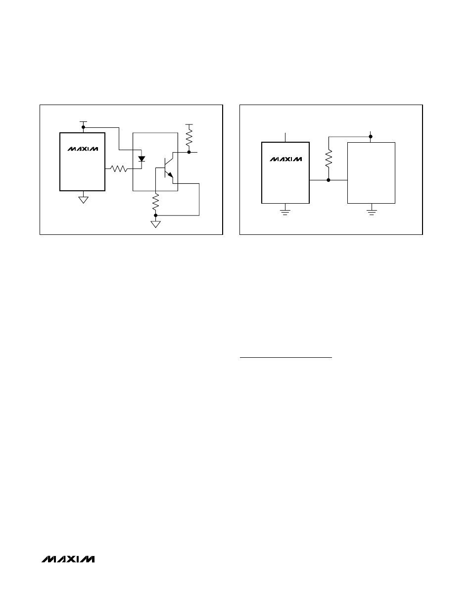
Galvanic Isolation
Use an optocoupler to isolate the MAX6676/MAX6677
whenever a high common-mode voltage is present.
Choose an optocoupler with equal turn-on and turn-off
times. Unequal turn-on/turn-off times produce an error
in the temperature reading (Figure 3).
Thermal Considerations
Self-heating may cause the temperature measurement
accuracy of the MAX6676/MAX6677 to degrade in
some applications. The quiescent dissipation and the
power dissipated by the digital output may cause
errors in obtaining the accurate temperature measure-
ment. The temperature errors depend on the thermal
conductivity of the package (SOT23, +140°C/W), the
mounting technique, and the airflow. Static dissipation
is typically 4.0µW operating at 5V with no load. For
example, an out load of 3mA creates a maximum error
of less than 0.1°C.
Multiple Logic Voltages
Use the MAX6676 open-drain output to drive devices
operating at supply voltages other than the MAX6676’s
V
CC
. As shown in Figure 4, connect a pullup resistor
from the other supply voltage to the MAX6676 output.
Limit the resistor’s current to less than 1mA, thus main-
taining an output low logic level of less than 200mV.
Chip Information
TRANSISTOR COUNT: 2096
PROCESS: BiCMOS
3.3V
DOUT
V
ISO
MAX6676AUT3
Figure 3. Galvanic Isolation Using an Optocoupler
V
CC
DOUT
MAX6676
V
DD
5.1k
Ω
Figure 4. Low-Voltage Logic