Detailed description, Applications information, Pin description – Rainbow Electronics MAX6677 User Manual
Page 4
MAX6676/MAX6677
Low-Voltage, 1.8kHz PWM Output Temperature
Sensors
4
_______________________________________________________________________________________
Detailed Description
The MAX6676/MAX6677 are high-accuracy, low-current
(80µA, typ) temperature sensors ideal for interfacing
with µCs or µPs. The MAX6676/MAX6677 convert the
ambient temperature into a ratiometric PWM output at a
nominal frequency of 1.8kHz (±20%) at +25°C.
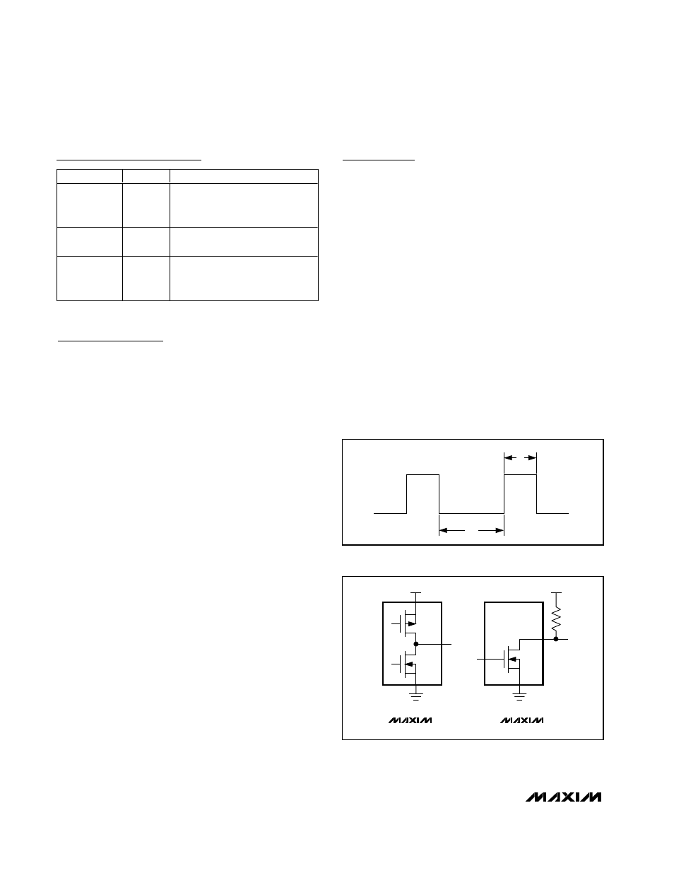
The time periods, t
1
(low) and t
2
(high) (Figure 1), are
easily read by a µP’s timer/counter port. To calculate
the temperature, use the following expression:
Temperature (°C) = 398.15 x (t
1
/ t
2
) - 273.15
The µC or µP measures the output of the MAX6676/
MAX6677 by counting t
1
and t
2
and computing the
temperature based on their ratio. The resolution of the
count is a function of the processor clock frequency
and the resolution of the counter. Always use the same
clock for t
1
and t
2
counters so that the temperature is
strictly based on a ratio of the two times, thus eliminat-
ing errors due to different clocks’ frequencies.
The MAX6677 (Figure 2a) has a push-pull output with
full CMOS output swings. The ability to source and sink
current allows the MAX6677 to drive capacitive loads
up to 100pF with less than 1°C error.
The MAX6676 (Figure 2b) has an open-drain output.
The output capacitance should be minimized in
MAX6676 applications because the sourcing current is
set by the pullup resistor. If the output capacitance
becomes too large, lengthy rise and fall times distort
the pulse width, resulting in inaccurate measurements.
Applications Information
Accurate temperature monitoring requires a good ther-
mal contact between the MAX6676/MAX6677 and the
object being monitored. A precise temperature mea-
surement depends on the thermal resistance between
the object being monitored and the MAX6676/
MAX6677 die. Heat flows in and out of plastic pack-
ages primarily through the leads. If the sensor is intend-
ed to measure the temperature of a heat-generating
component on the circuit board, mount the device as
close as possible to that component and share the
ground traces (if they are not too noisy) with the com-
ponent. This maximizes the heat transfer from the com-
ponent to the sensor.
Power Supply from µP Port Pin
The low quiescent current of the MAX6676/MAX6677
enables them to be powered from a logic line, which
meets the requirements for supply voltage range. This
provides a simple shutdown function to totally eliminate
quiescent current by taking the logic line low. The logic
line must be able to withstand the 0.1µF power-supply
bypass capacitance.
Pin Description
PIN
NAME
FUNCTION
1
DOUT
Digital Output Pin. The duty
cycle of the output waveform is
modulated by temperature.
2, 4, 5, 6
GND
Ground. All four ground pins
must be connected to GND.
3
V
CC
Supply Voltage. It is
recommended bypassing V
CC
to GND with a 0.1µF capacitor.
t
1
t
2
Figure 1. MAX6676/MAX6677 PWM Output
V
CC
DOUT
DOUT
P
N
(a)
(b)
N
V
CC
MAX6676
MAX6677
Figure 2. Output Configurations