Rainbow Electronics MAX5085 User Manual
Page 8
MAX5084/MAX5085
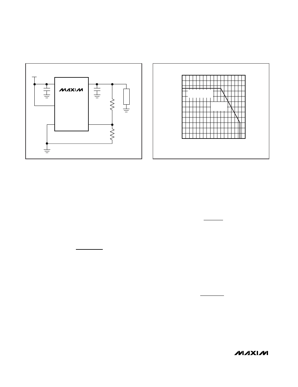
Use Figure 3 to determine the allowable package dissi-
pation for a given ambient temperature. Alternately, use
the following formula to calculate the allowable pack-
age dissipation:
After determining the allowable package dissipation,
calculate the maximum output current using the follow-
ing formula:
The above equations do not include the negligible
power dissipation from self-heating due to the device’s
ground current.
Example 1:
T
A
= +85°C
V
IN
= 14V
V
OUT
= 5V
Find the maximum allowable output current. First calcu-
late package dissipation at the given temperature as
follows:
P
D
= 1.905W – 0.0238W/°C (85°C – 70°C) = 1.548W
Then determine the maximum output current:
Example 2:
T
A
= +125°C
V
IN
= 14V
V
OUT
= 3.3V
Calculate package dissipation at the given temperature
as follows:
P
D
= 1.905W – 0.0238W/°C (125°C – 70°C) = 596mW
And establish the maximum output current:
Example 3:
T
A
= +50°C
V
IN
= 9V
V
OUT
= 5V
I
mW
V
V
mA
OUT MAX
(
)
.
=
−
=
596
14
3 3
56
IOUT MAX
W
V
V
mA
(
)
.
=
−
=
1 548
14
5
172
I
OUT(MAX)
=
P
D
V
IN
– V
OUT
≤ 200m A
P
W for T
C
W
W C x T
C for
C
T
C
D
A
A
A
.
.
– .
/
(
)
=
≤ + °
°
− °
+ ° <
≤ +
°
1 905
70
1 905
0 0238
70
70
125
65V, 200mA, Low-Quiescent-Current
Linear Regulators in TDFN
8
_______________________________________________________________________________________
V
IN
= 6.5V
TO 65V
V
OUT
= 2.5V TO 11V
(200mA)
10
µF
10
µF
OUT
OUT_SENSE
SET
IN
R1
LOAD
R2
EN
GND
MAX5084
MAX5085
Figure 2. Adjustable Output Voltage Operation
MAX5084 fig03
TEMPERATURE (
°C)
P
D
(W)
20
40
60
80 100 120 140
-20
0
0.6
0.4
0.2
0.8
1.0
1.2
1.4
1.6
1.8
2.0
2.2
2.4
0
-40
MAXIMUM POWER
1.905W
DERATE
23.8mW/
°C
Figure 3. Calculated Maximum Power Dissipation vs.
Temperature