Rainbow Electronics T89C51IC2 User Manual
Page 6
6
T89C51IC2
Rev. C – 3-Dec-01
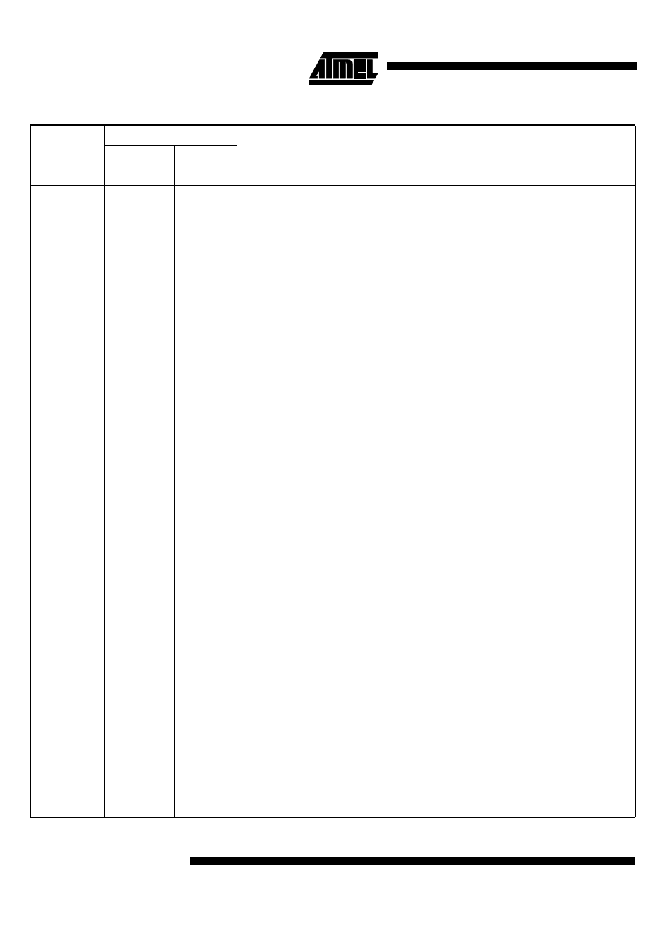
Table 1. Pin Description for 40/44 pin packages
Mnemonic
Pin Number
Type
Name and Function
PLCC44
VQFP44 1.4
V
SS
22
16
I
Ground: 0V reference
V
CC
44
38
I
Power Supply: This is the power supply voltage for normal, idle and power-down
operation
P0.0-P0.7
43-36
37-30
I/O
Port 0: Port 0 is an open-drain, bidirectional I/O port. Port 0 pins that have 1s written to
them float and can be used as high impedance inputs. Port 0 must be polarized to V
CC
or V
SS
in order to prevent any parasitic current consumption. Port 0 is also the
multiplexed low-order address and data bus during access to external program and
data memory. In this application, it uses strong internal pull-up when emitting 1s. Port 0
also inputs the code bytes during EPROM programming. External pull-ups are required
during program verification during which P0 outputs the code bytes.
P1.0-P1.7
2-9
40-44
1-3
I/O
Port 1: Port 1 is an 8-bit bidirectional I/O port with internal pull-ups. Port 1 pins that
have 1s written to them are pulled high by the internal pull-ups and can be used as
inputs. As inputs, Port 1 pins that are externally pulled low will source current because
of the internal pull-ups. Port 1 also receives the low-order address byte during memory
programming and verification.
Alternate functions for T89C51IC2 Port 1 include:
2
40
I/O
P1.0: Input / Output
I/O
T2 (P1.0): Timer/Counter 2 external count input/Clockout
I
XTALB1 (P1.0): Sub Clock input to the inverting oscillator amplifier
3
41
I/O
P1.1: Input / Output
I
T2EX: Timer/Counter 2 Reload/Capture/Direction Control
I
SS: SPI Slave Select
4
42
I/O
P1.2: Input / Output
I
ECI: External Clock for the PCA
5
43
I/O
P1.3: Input / Output
I/O
CEX0: Capture/Compare External I/O for PCA module 0
6
44
I/O
P1.4: Input / Output
I/O
CEX1: Capture/Compare External I/O for PCA module 1
7
1
I/O
P1.5: Input / Output
I/O
CEX2: Capture/Compare External I/O for PCA module 2
I/O
MISO: SPI Master Input Slave Output line
When SPI is in master mode, MISO receives data from the slave peripheral. When SPI
is in slave mode, MISO outputs data to the master controller.
8
2
I/O
P1.6: Input / Output
I/O
CEX3: Capture/Compare External I/O for PCA module 3
I/O
SCK: SPI Serial Clock
SCK outputs clock to the slave peripheral
9
3
I/O
P1.7: Input / Output: