Pin description (continued), Detailed description – Rainbow Electronics MAX16043 User Manual
Page 7
MAX16041/MAX16042/MAX16043
Dual-/Triple-/Quad-Voltage, Capacitor-
Adjustable, Sequencing/Supervisory Circuits
_______________________________________________________________________________________
7
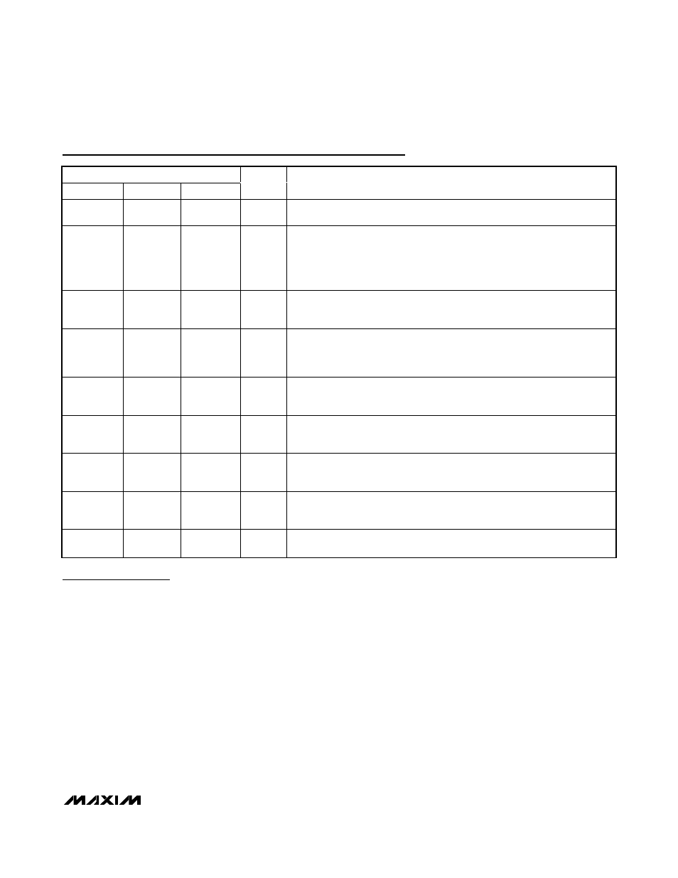
Pin Description (continued)
PIN
MAX16041
MAX16042
MAX16043
NAME
FUNCTION
11
14
17
OUT1
Output 1. When the voltage at IN1 is below its threshold or EN1 goes low,
OUT1 goes low.
12
15
18
RESET
Active-Low Reset Output.
RESET asserts low when any of the monitored
voltages (IN_) falls below its respective threshold, any EN_ goes low, or
MR is
asserted.
RESET remains asserted for the reset timeout period after all of the
monitored voltages exceed their respective threshold, all EN_ are high, all
OUT_ are high, and
MR is deasserted.
13
16
19
MR
Active-Low Manual Reset Input. Pull
MR low to assert RESET low. RESET
remains low for the reset timeout period after
MR is deasserted (as long as all
OUT_ are high).
14
17
20
CRESET
Capacitor-Adjustable Reset Delay Input. Connect an external capacitor from
CRESET to GND to set the reset timeout period or connect to V
CC
for the
default 140ms minimum reset timeout period. Leave CRESET open for internal
propagation delay.
—
—
21
CDLY4
Capacitor-Adjustable Delay Input 4. Connect an external capacitor from
CDLY4 to GND to set the IN4 to OUT4 (and EN4 to OUT4) delay period.
Leave CDLY4 open for internal propagation delay.
—
18
22
CDLY3
Capacitor-Adjustable Delay Input 3. Connect an external capacitor from
CDLY3 to GND to set the IN3 to OUT3 (and EN3 to OUT3) delay period.
Leave CDLY3 open for internal propagation delay.
15
19
23
CDLY2
Capacitor-Adjustable Delay Input 2. Connect an external capacitor from
CDLY2 to GND to set the IN2 to OUT2 (and EN2 to OUT2) delay period.
Leave CDLY2 open for internal propagation delay.
16
20
24
CDLY1
Capacitor-Adjustable Delay Input 1. Connect an external capacitor from
CDLY1 to GND to set the IN1 to OUT1 (and EN1 to OUT1) delay period.
Leave CDLY1 open for internal propagation delay.
—
—
—
EP
Exposed Pad. EP is internally connected to GND. Connect EP to the
ground plane.
Detailed Description
The MAX16041/MAX16042/MAX16043 are low-voltage,
accurate, dual-/triple-/quad-voltage microprocessor
(µP) supervisors in a small TQFN package. These
devices provide supervisory and sequencing functions
for complex multivoltage systems. The MAX16041 mon-
itors two voltages, the MAX16042 monitors three volt-
ages, and the MAX16043 monitors four voltages.
The MAX16041/MAX16042/MAX16043 offer indepen-
dent outputs and enable functions for each monitored
voltage. This configuration allows the device to operate as
four separate supervisory circuits or be daisy-chained
together to allow controlled sequencing of power supplies
during power-up initialization. When all of the monitored
voltages exceed their respective thresholds, an inde-
pendent reset output deasserts to allow the system
processor to operate.
These devices offer enormous flexibility as there are
nine threshold options that are selected through two
threshold-select logic inputs. Each monitor circuit also
offers an independent enable input to allow both digital
and analog control of each monitor output. A tolerance
select input allows these devices to be used in systems
requiring 5% or 10% power-supply tolerances. In addi-
tion, the time delays and reset timeout can be adjusted
using small capacitors. There is also a fixed 140ms
minimum reset timeout feature.