Chip information, Table 1. typical harmonic distortion – Rainbow Electronics MAX7480 User Manual
Page 8
MAX7480
8th-Order, Lowpass, Butterworth,
Switched-Capacitor Filter
Maxim cannot assume responsibility for use of any circuitry other than circuitry entirely embodied in a Maxim product. No circuit patent licenses are
implied. Maxim reserves the right to change the circuitry and specifications without notice at any time.
8
_____________________Maxim Integrated Products, 120 San Gabriel Drive, Sunnyvale, CA 94086 408-737-7600
© 1999 Maxim Integrated Products
Printed USA
is a registered trademark of Maxim Integrated Products.
Anti-Aliasing and Post-DAC Filtering
When using the MAX7480 for anti-aliasing or post-DAC
filtering, synchronize the DAC and the filter clocks. If
the clocks are not synchronized, beat frequencies may
alias into the passband.
The high clock-to-corner frequency ratio (100:1) also
eases the requirements of pre- and post-SCF filtering.
At the input, a lowpass filter prevents the aliasing of fre-
quencies around the clock frequency into the pass-
band. At the output, a lowpass filter attenuates the
clock feedthrough.
A high clock to corner-frequency ratio allows a simple
RC lowpass filter, with the cutoff frequency set above
the SCF corner frequency to provide input anti-aliasing
and reasonable output clock attenuation.
Harmonic Distortion
Harmonic distortion arises from nonlinearities within the
filter. These nonlinearities generate harmonics when a
pure sine wave is applied to the filter input. Table 1 lists
the MAX7480’s typical harmonic-distortion values with
a 10k
Ω
load at T
A
= +25°C.
V
DD
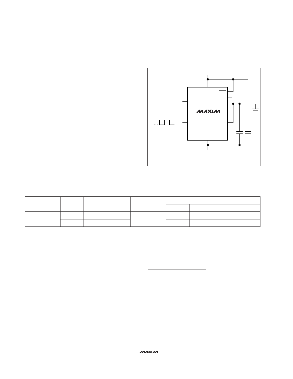
V+ = +2.5V
V- = -2.5V
IN
CLK
GND
INPUT
OUTPUT
OUT
0.1
µ
F
CLOCK
*DRIVE SHDN TO V- FOR LOW-POWER SHUTDOWN MODE.
SHDN
COM
OS
0.1
µ
F
MAX7480
*
V+
V-
Figure 4. Dual-Supply Operation
5th
3rd
-89
-68
-93
-73
200
100
f
CLK
(kHz)
4th
2nd
-85
-91
TYPICAL HARMONIC DISTORTION (dB)
-82
-89
4
2
1
MAX7480
V
IN
(Vp-p)
f
C
(kHz)
FILTER
400
200
f
IN
(Hz)
Table 1. Typical Harmonic Distortion
TRANSISTOR COUNT: 1116
Chip Information