Rainbow Electronics MAX7480 User Manual
Page 6
MAX7480
8th-Order, Lowpass, Butterworth,
Switched-Capacitor Filter
6
_______________________________________________________________________________________
NAME
FUNCTION
1
COM
Common Input Pin. Biased internally at mid-supply. Bypass externally to GND with a 0.1µF capacitor. To
override internal biasing, drive with an external supply.
2
IN
Filter Input
PIN
3
GND
Ground
4
V
DD
+5V Supply Input
8
CLK
Clock Input. To override the internal oscillator, connect to an external clock; otherwise, connect an external
capacitor (C
OSC
) from CLK to GND to set the internal oscillator frequency.
7
SHDN
Shutdown Input. Drive low to enable shutdown mode; drive high or connect to V
DD
for normal operation.
6
OS
Offset Adjust Input. To adjust output offset, bias OS externally. Connect OS to COM if no offset adjustment is
needed. Refer to
Offset and Common-Mode Input Adjustment
section.
5
OUT
Filter Output
Pin Description
_______________Detailed Description
The MAX7480 Butterworth filter operates with a 100:1
clock-to-corner frequency ratio and a 2kHz maximum
corner frequency.
Lowpass Butterworth filters provide a maximally flat
passband response, making them ideal for instrumen-
tation applications that require minimum deviation from
the DC gain throughout the passband.
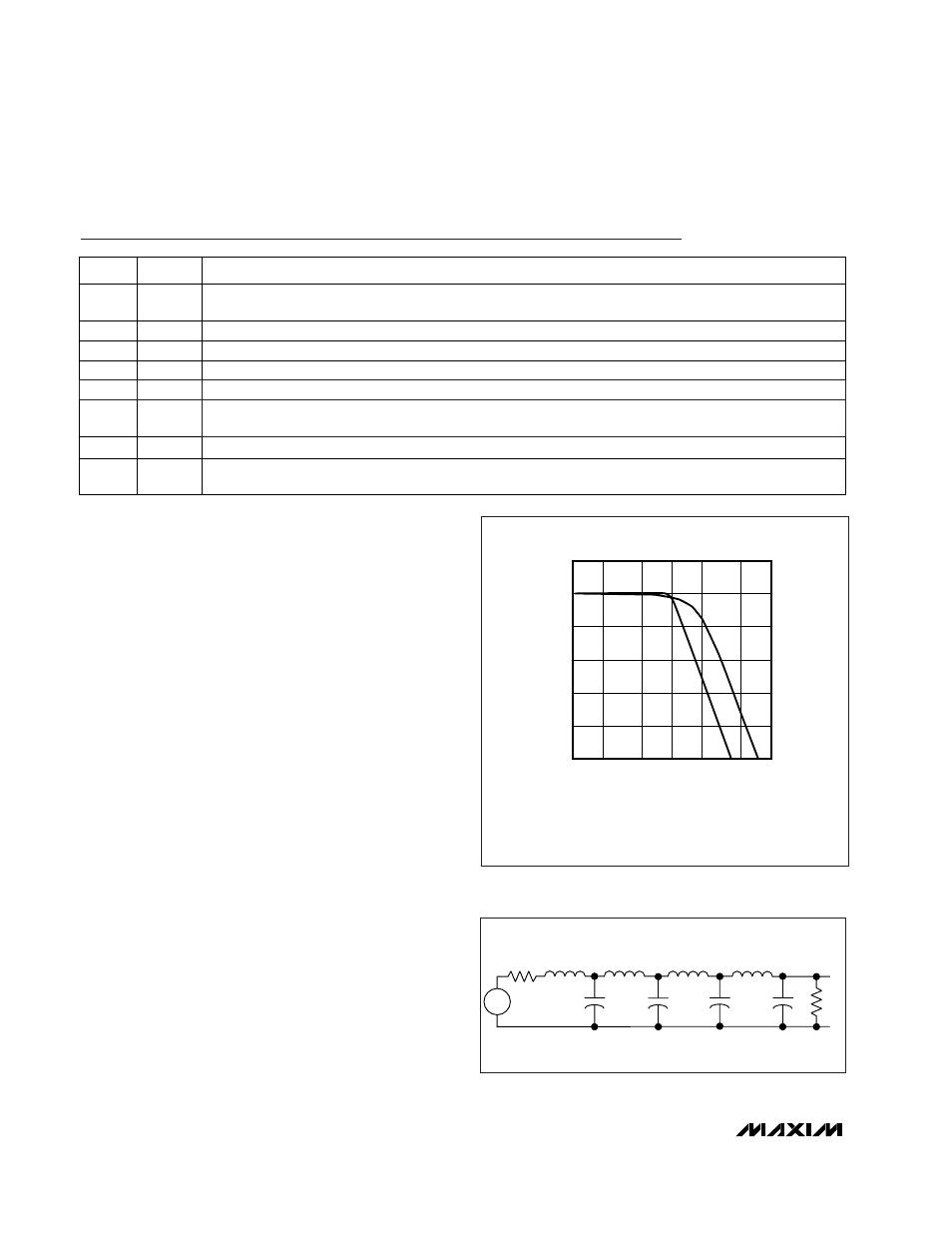
Figure 1 shows the difference between Bessel and
Butterworth filter frequency responses. With the filter
cutoff frequencies set at 1kHz, trace A shows the
Bessel filter response and trace B shows the
Butterworth filter response.
Background Information
Most switched-capacitor filters (SCFs) are designed
with biquadratic sections. Each section implements two
filtering poles, and the sections are cascaded to pro-
duce higher-order filters. The advantage to this
approach is ease of design. However, this type of
design is highly sensitive to component variations if any
section’s Q is high. An alternative approach is to emu-
late a passive network using switched-capacitor inte-
grators with summing and scaling. Figure 2 shows a
basic 8th-order ladder filter structure.
A switched-capacitor filter such as the MAX7480 emu-
lates a passive ladder filter. The filter’s component sen-
sitivity is low when compared to a cascaded biquad
design, because each component affects the entire fil-
ter shape, not just one pole-zero pair. In other words, a
mismatched component in a biquad design will have a
concentrated error on its respective poles, while the
same mismatch in a ladder filter design results in an
error distributed over all poles.
-100
-60
-80
-20
-40
0
20
0.1
0.5
1
0.2
A
B
2
5
10
FREQUENCY (kHz)
GAIN (dB)
A: BESSEL FILTER RESPONSE; f
C
= 1kHz
B: BUTTERWORTH FILTER RESPONSE; f
C
= 1kHz
Figure 1. Bessel vs. Butterworth Filter Frequency Response
L3
L5
L7
C8
R2
C4
C2
V
IN
+
-
V
0
L1
R1
C6
Figure 2. 8th-Order Ladder Filter Network