Pin description – Rainbow Electronics MAX19506 User Manual
Page 12
MAX19506
Dual-Channel, 8-Bit, 100Msps ADC
12
______________________________________________________________________________________
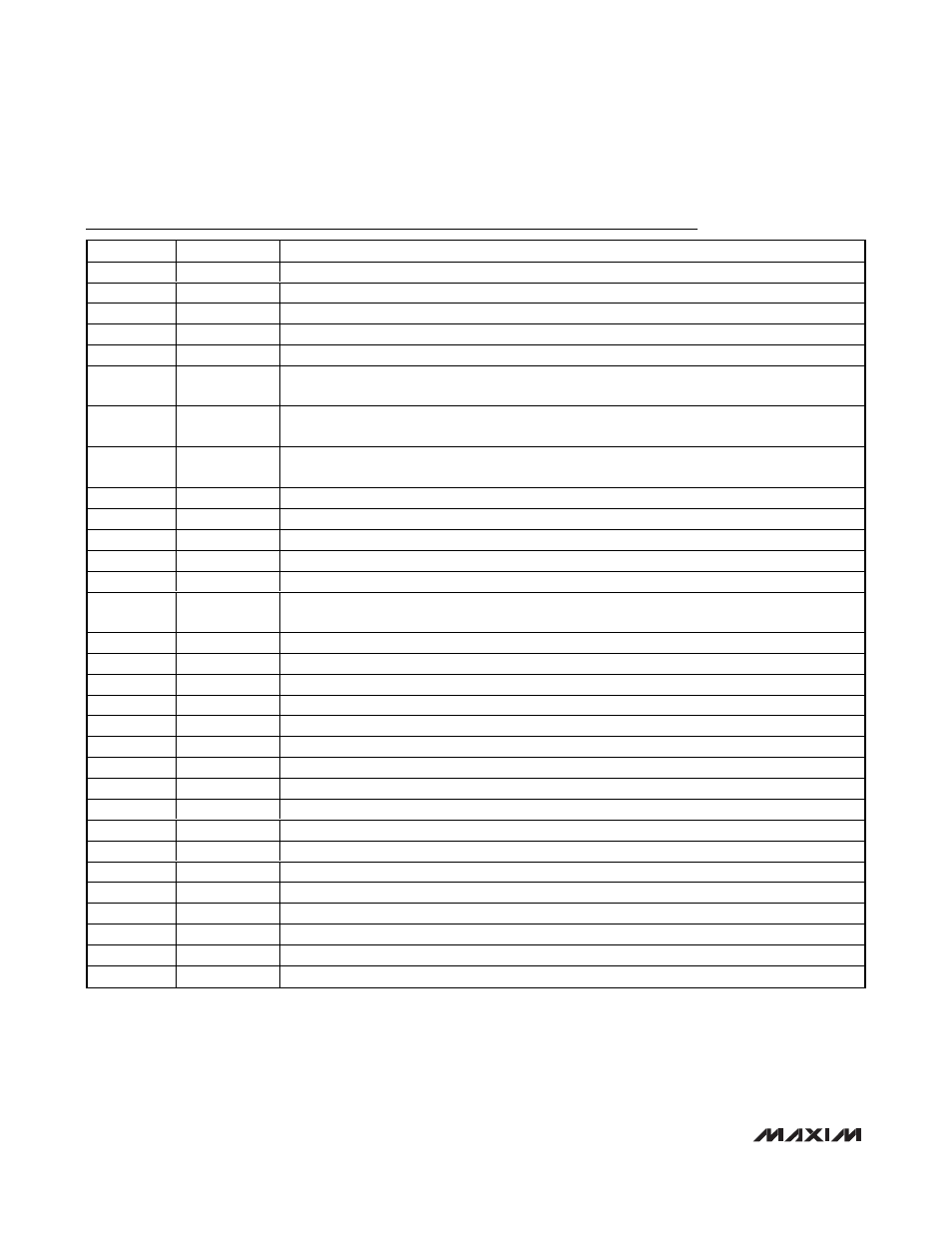
Pin Description
PIN
NAME
FUNCTION
1, 12, 13, 48
AVDD
Analog Supply Voltage. Bypass each AVDD input pair (1, 48) and (12, 13) to GND with 0.1µF.
2
CMA
Channel A Common-Mode Input-Voltage Reference
3
INA+
Channel A Positive Analog Input
4
INA-
Channel A Negative Analog Input
5
SPEN
Active-Low SPI Enable. Drive high to enable parallel programming mode.
6
REFIO
Reference Input/Output. To use internal reference, bypass to GND with a > 0.1µF capacitor. See
the Reference Input/Output (REFIO) section for external reference adjustment.
7
SHDN
Active-High Power-Down. If
SPEN is high (parallel programming mode), a register reset is initiated
on the falling edge of SHDN.
8, 21, 22, 32,
33
I.C.
Internally Connected. Leave unconnected.
9
INB+
Channel B Positive Analog Input
10
INB-
Channel B Negative Analog Input
11
CMB
Channel B Common-Mode Input-Voltage Reference
14
SYNC
Clock-Divider Mode Synchronization Input
15
CLK+
Clock Positive Input
16
CLK-
Clock Negative Input. If CLK- is connected to ground, CLK+ is a single-ended logic-level clock
input. Otherwise, CLK+/CLK- are self-biased differential clock inputs.
17, 18
GND
Ground. Connect all ground inputs and EP (exposed pad) together.
19
DORB
Channel B Data Over Range
20
DCLKB
Channel B Data Clock
23
D0B
Channel B Three-State Digital Output, Bit 0 (LSB)
24
D1B
Channel B Three-State Digital Output, Bit 1
25, 36
OVDD
Digital Supply Voltage. Bypass each OVDD input to GND with a 0.1µF capacitor.
26
D2B
Channel B Three-State Digital Output, Bit 2
27
D3B
Channel B Three-State Digital Output, Bit 3
28
D4B
Channel B Three-State Digital Output, Bit 4
29
D5B
Channel B Three-State Digital Output, Bit 5
30
D6B
Channel B Three-State Digital Output, Bit 6
31
D7B
Channel B Three-State Digital Output, Bit 7 (MSB)
34
D0A
Channel A Three-State Digital Output, Bit 0 (LSB)
35
D1A
Channel A Three-State Digital Output, Bit 1
37
D2A
Channel A Three-State Digital Output, Bit 2
38
D3A
Channel A Three-State Digital Output, Bit 3
39
D4A
Channel A Three-State Digital Output, Bit 4