Pin description, General description, Table 1. factory-programmed threshold range – Rainbow Electronics MAX6504 User Manual
Page 4
MAX6501–MAX6504
Low-Cost, +2.7V to +5.5V, Micropower
Temperature Switches in SOT23 and TO-220
4
_______________________________________________________________________________________
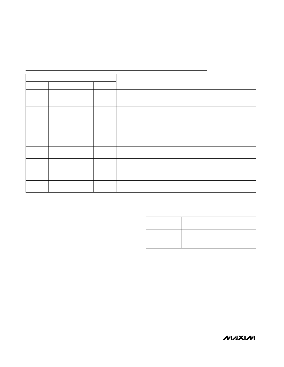
Pin Description
1, 2
1, 2
Ground. Not internally connected. Tie both ground pins togeth-
er close to the chip. Pin 2 provides the lowest thermal resis-
tance to the die.
1, 2
PIN
1, 2
GND
3
3
Hysteresis Input. Connect HYST to GND for +2°C hysteresis, or
connect to V
CC
for +10°C hysteresis.
3
3
HYST
4
4
Supply Input (+2.7V to +5.5V)
5
—
Open-Drain, Active-Low Output.
TOVER goes low when the die
temperature exceeds the factory-programmed temperature
threshold. Connect to a 100k
Ω pull-up resistor. May be pulled
up to a voltage higher than V
CC
.
—
—
TOVER
4
4
V
CC
—
5
Push-Pull Active-High Output. TOVER goes high when the die tem-
perature exceeds the factory-programmed temperature threshold.
—
—
Open-Drain, Active-Low Output.
TUNDER goes low when the
die temperature goes below the factory-programmed tempera-
ture threshold. Connect to a 100k
Ω pull-up resistor. May be
pulled up to a voltage higher than V
CC
.
5
—
TUNDER
—
—
Push-Pull Active-High Output. TUNDER goes high when the die tem-
perature falls below the factory-programmed temperature threshold.
—
5
TUNDER
—
—
TOVER
MAX6502
MAX6501
MAX6503
MAX6504
NAME
FUNCTION
________________General Description
The MAX6501–MAX6504 fully integrated temperature
switches incorporate two temperature-dependent refer-
ences and a comparator. One reference exhibits a pos-
itive temperature coefficient and the other a negative
temperature coefficient (Figure 1). The temperature at
which the two reference voltages are equal determines
the temperature trip point. Pin-selectable +2°C or
+10°C hysteresis keeps the output from oscillating
when the die temperature approaches the threshold
temperature. The MAX6501/MAX6503 have an active-
low, open-drain output structure that can only sink cur-
rent. The MAX6502/MAX6504 have an active-high,
push-pull output structure that can sink or source cur-
rent. The internal power-on reset circuit guarantees the
output is at T
TH
= +25°C state at start-up for 50µs.
The MAX6501–MAX6504 are available with factory-
preset temperature thresholds from -45°C to +115°C in
10°C increments. Table 1 lists the available temperature
threshold ranges. The MAX6501/MAX6503 outputs are
intended to interface with a microprocessor (µP) reset
input (Figure 2). The MAX6502/MAX6504 outputs are
intended for applications such as driving a fan control
(Figure 3).
Hysteresis Input
The HYST pin is a CMOS-compatible input that selects
hysteresis at either a high level (+10°C for HYST = V
CC
)
or a low level (+2°C for HYST = GND). Hysteresis pre-
vents the output from oscillating when the temperature
approaches the trip point. The HYST pin should not
float. Drive HYST close to ground or V
CC
. Other input
voltages cause increased supply current. The actual
amount of hysteresis depends on the part’s pro-
grammed trip threshold. (See the Typical Operating
Characteristics graphs.)
Table 1. Factory-Programmed Threshold
Range
+35°C < T
TH
< +115°C
+35°C < T
TH
< +115°C
THRESHOLD (T
TH
) RANGE
-45°C < T
TH
< +15°C
-45°C < T
TH
< +15°C
MAX6503
MAX6504
MAX6501
MAX6502
PART