Pin description – Rainbow Electronics MAX6654 User Manual
Page 5
MAX6654
1°C Accurate Remote/Local Temperature
Sensor with SMBus Serial Interface
_______________________________________________________________________________________
5
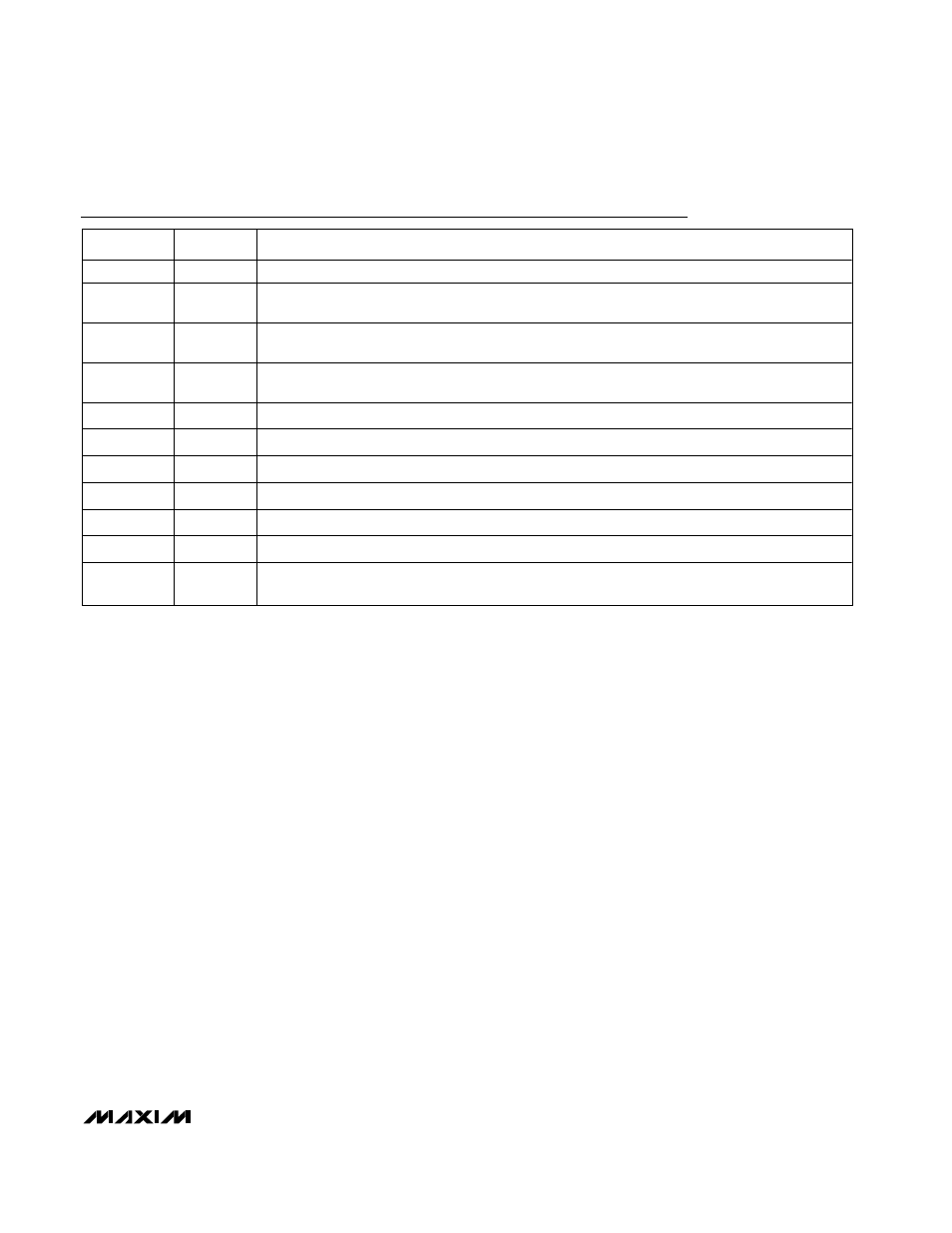
Pin Description
PIN
NAME
FUNCTION
1, 5, 9, 13, 16
N.C.
No Connection. Not internally connected. May be used for PC board trace routing.
2
V
CC
Supply Voltage Input. +3.0V to +5.5V. Bypass to GND with a 0.1
µF capacitor. A 200Ω series
resistor is recommended but not required for additional noise filtering.
3
DXP
Combined Current Source and ADC Positive Input for Remote-Junction Channel. If a remote-
sensing junction is not used, connect DXP to DXN.
4
DXN
Combined Current Sink and ADC Negative Input. DXN is internally biased to a diode voltage above
ground.
6
ADD1
SMBus Slave Address Select Input. ADD0 and ADD1 are sampled upon power-up.
7, 8
GND
Ground
10
ADD0
SMBus Slave Address Select Input. ADD0 and ADD1 are sampled upon power-up.
11
ALERT
SMBus Alert (Interrupt) Output. Open drain.
12
SMBDATA
SMBus Serial-Data Input/Output. Open drain.
14
SMBCLK
SMBus Serial-Clock Input
15
STBY
Hardware standby input. Temperature and comparison threshold data are retained in standby
mode. Low = standby mode, high = operating mode.