Chip information, Table 8. conversion-rate control byte, Table 9. slave address decoding (add0 and add1) – Rainbow Electronics MAX6654 User Manual
Page 15
Power-Up Defaults:
• Interrupt latch is cleared.
• Address select pins are sampled.
• ADC begins autoconverting at a 0.25Hz rate.
• Command byte is set to 00h to facilitate quick
remote Receive Byte queries.
• T
HIGH
and T
LOW
registers are set to max and min
limits, respectively.
MAX6654
1°C Accurate Remote/Local Temperature
Sensor with SMBus Serial Interface
______________________________________________________________________________________
15
DATA
CONVERSION RATE (Hz)
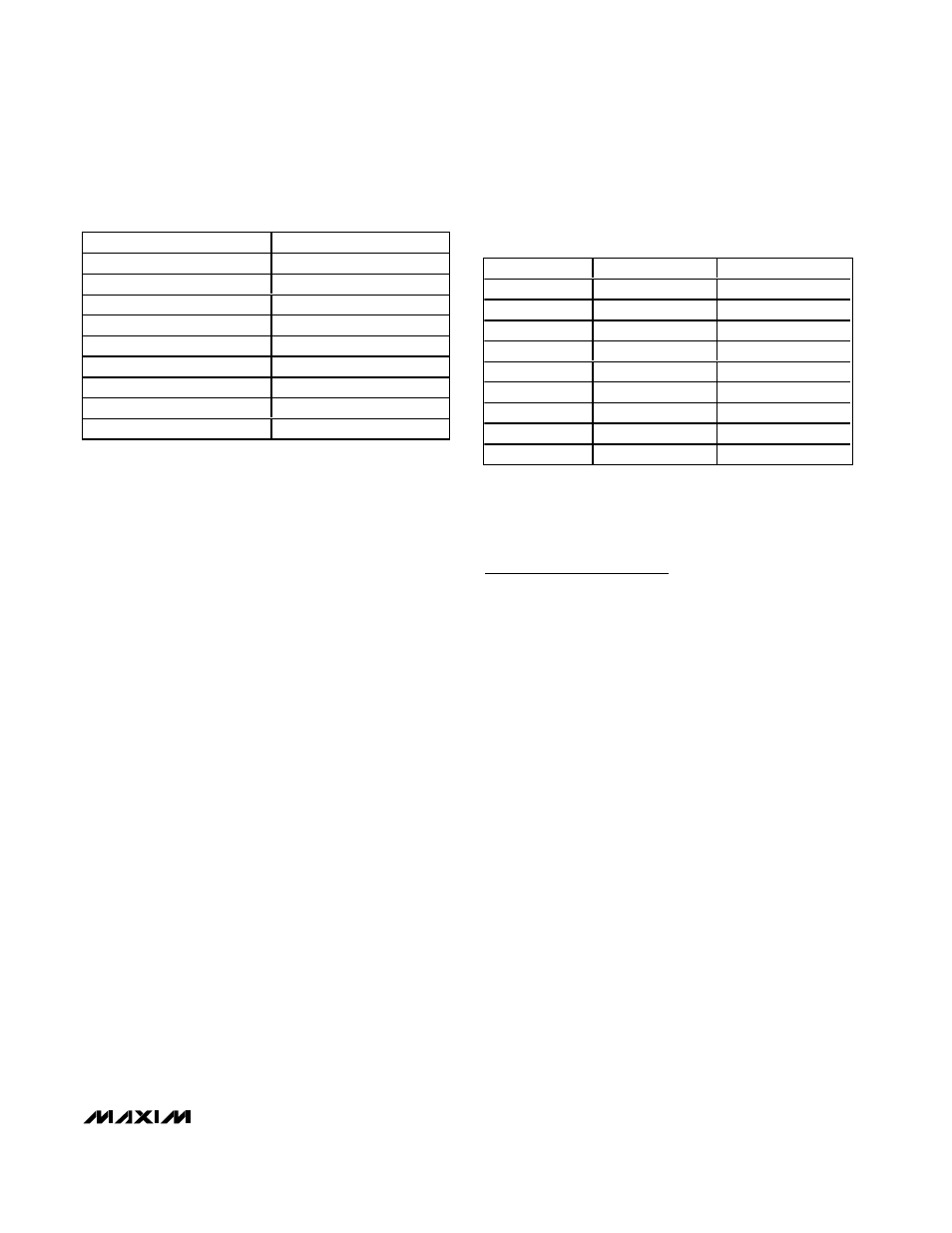
00h
0.0625
01h
0.125
02h
0.25
03h
0.5
04h
1
05h
2
06h
4
07h
8
08h-FFh
Reserved
Table 8. Conversion-Rate Control Byte
ADD0
ADD1
ADDRESS
0
0
0011 000
0
High-Z
0011 001
0
1
0011 010
High-Z
0
0101 001
High-Z
High-Z
0101 010
High-Z
1
0101 011
1
0
1001 100
1
High-Z
1001 101
1
1
1001 110
Table 9. Slave Address Decoding (ADD0
and ADD1)
Note: High-Z means that the pin is left unconnected and float-
ing.
Chip Information
TRANSISTOR COUNT: 12,504
- MAX5151 (16 pages)
- MAXQ3108 (64 pages)
- MAX5661 (39 pages)
- MAX6691 (7 pages)
- MAX5362 (12 pages)
- ADC10158 (26 pages)
- MAX8922L (14 pages)
- MAX8596Z (8 pages)
- MAX7491 (18 pages)
- MAX15040 (15 pages)
- MAX5177 (16 pages)
- ADC08138 (22 pages)
- MAX5961 (42 pages)
- T89C51RD2 (86 pages)
- MAX16055 (9 pages)
- MAX6659 (17 pages)
- ADC0820 (20 pages)
- MAX6678 (19 pages)
- MAX8884Z (15 pages)
- MAX16915 (9 pages)
- MAX8620 (18 pages)
- MAX5144 (12 pages)
- MAX6670 (8 pages)
- MAX8760 (39 pages)
- W78C32C (14 pages)
- MX7533 (8 pages)
- MAX8727 (13 pages)
- MAX9053 (15 pages)
- W78C54 (16 pages)
- MAX8614B (15 pages)
- W90N740 (219 pages)
- MAX6626 (13 pages)
- ADC10738 (30 pages)
- MAX17000 (31 pages)
- MAX5051 (21 pages)
- MAXQ1004 (18 pages)
- MAX6871 (51 pages)
- MX7847 (12 pages)
- MAX6608 (6 pages)
- MAX17083 (15 pages)
- MAX6641 (17 pages)
- MAX5251 (16 pages)
- MAX6338 (8 pages)
- MAX6690 (16 pages)
- MAX8668 (18 pages)