Rainbow Electronics MAX5253 User Manual
Page 9
In shutdown mode, the MAX5253 output amplifiers and
the reference inputs enter a high-impedance state. The
serial interface remains active. Data in the input regis-
ters is retained in shutdown, allowing the MAX5253 to
recall the output states prior to entering shutdown. Exit
shutdown mode by either recalling the previous config-
uration or by updating the DACs with new data. When
powering up the device or bringing it out of shutdown,
allow 20µs for the outputs to stabilize.
Serial-Interface Configurations
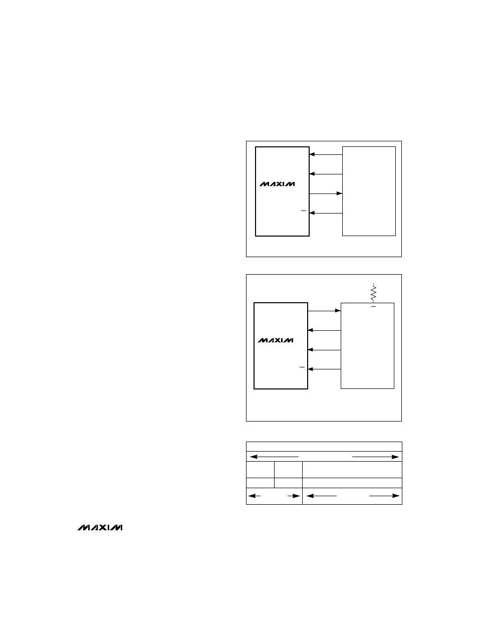
The MAX5253’s 3-wire serial interface is compatible
with both Microwire™ (Figure 2) and SPI™/QSPI™
(Figure 3). The serial input word consists of two address
bits and two control bits followed by 12 data bits
(MSB first), as shown in Figure 4. The 4-bit address/
control code determines the MAX5253’s response out-
lined in Table 1. The connection between DOUT and
the serial-interface port is not necessary, but may be
used for data echo. Data held in the MAX5253’s shift
register can be shifted out of DOUT and returned to the
microprocessor (µP) for data verification.
The MAX5253’s digital inputs are double buffered.
Depending on the command issued through the serial
interface, the input register(s) can be loaded without
affecting the DAC register(s), the DAC register(s) can
be loaded directly, or all four DAC registers can be
updated simultaneously from the input registers
(Table 1).
Serial-Interface Description
The MAX5253 requires 16 bits of serial data. Table 1
lists the serial-interface programming commands. For
certain commands, the 12 data bits are “don’t cares.”
Data is sent MSB first and can be sent in two 8-bit
packets or one 16-bit word (
CS must remain low until
16 bits are transferred). The serial data is composed of
two DAC address bits (A1, A0) and two control bits
(C1,C0), followed by the 12 data bits D11…D0 (Figure
4).The 4-bit address/control code determines:
•
The register(s) to be updated
•
The clock edge on which data is to be clocked out
via the serial-data output (DOUT)
•
The state of the user-programmable logic output
(UPO)
•
If the part is to go into shutdown mode (assuming
PDL is high)
•
How the part is configured when exiting shutdown
mode.
MAX5253
+3V, Quad, 12-Bit Voltage-Output DAC
with Serial Interface
_______________________________________________________________________________________
9
SCLK
DIN
DOUT*
CS
SK
SO
SI*
I/O
MAX5253
MICROWIRE
PORT
*THE DOUT-SI CONNECTION IS NOT REQUIRED FOR WRITING TO THE MAX5253,
BUT MAY BE USED FOR READBACK PURPOSES.
Figure 2. Connections for Microwire
DOUT*
DIN
SCLK
CS
MISO*
MOSI
SCK
I/O
SPI/QSPI
PORT
SS
+3.3V
CPOL = 0, CPHA = 0
*THE DOUT-MISO CONNECTION IS NOT REQUIRED FOR WRITING TO THE MAX5253,
BUT MAY BE USED FOR READBACK PURPOSES.
MAX5253
Figure 3. Connections for SPI/QSPI
Figure 4. Serial-Data Format
MSB ..................................................................................LSB
16 Bits of Serial Data
Address
Bits
Control
Bits
Data Bits
MSB.............................................LSB
A1 A0
C1 C0
D11................................................D0
12 Data Bits
4 Address/
Control Bits