Applications information – Rainbow Electronics MAX5253 User Manual
Page 13
__________Applications Information
Unipolar Output
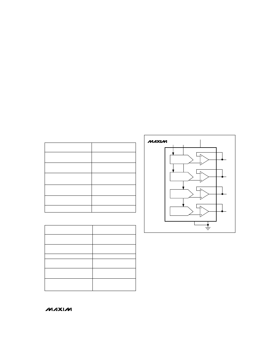
For a unipolar output, the output voltages and the refer-
ence inputs have the same polarity. Figure 9 shows the
MAX5253 unipolar output circuit, which is also the typi-
cal operating circuit. Table 2 lists the unipolar output
codes.
For rail-to-rail outputs, see Figure 10. This circuit shows
the MAX5253 with the output amplifiers configured with
a closed-loop gain of +2.6 to provide 0V to 3.25V full-
scale range when a 1.25V reference is used.
Bipolar Output
The MAX5253 outputs can be configured for bipolar
operation using Figure 11’s circuit.
V
OUT
= V
REF
[(2NB / 4096) - 1]
where NB is the numeric value of the DAC’s binary
input code. Table 3 shows digital codes (offset binary)
and corresponding output voltages for Figure 11’s
circuit.
MAX5253
+3V, Quad, 12-Bit Voltage-Output DAC
with Serial Interface
______________________________________________________________________________________
13
Table 2. Unipolar Code Table
Table 3. Bipolar Code Table
DAC CONTENTS
ANALOG OUTPUT
MSB
LSB
4095
1 1 1 1
1 1 1 1
1 1 1 1
+V
REF
(
———
)
4096
2049
1000
0000
0001
+V
REF
(
———
)
4096
2048
+V
REF
1 0 0 0
0 0 0 0
0 0 0 0
+V
REF
(
———
)
= ————
4096
2
2047
0 1 1 1
1 1 1 1
1 1 1 1
+V
REF
(
———
)
4096
1
0 0 0 0
0 0 0 0
0 0 0 1
+V
REF
(
———
)
4096
0 0 0 0
0 0 0 0
0 0 0 0
0V
DAC CONTENTS
ANALOG OUTPUT
MSB
LSB
2047
1 1 1 1
1 1 1 1
1 1 1 1
+V
REF
(
———
)
2048
1
1000
0000
0001
+V
REF
(
———
)
2048
1 0 0 0
0 0 0 0
0 0 0 0
0V
1
0 1 1 1
1 1 1 1
1 1 1 1
-V
REF
(
———
)
2048
2047
0 0 0 0
0 0 0 0
0 0 0 1
-V
REF
(
———
)
2048
2048
0 0 0 0
0 0 0 0
0 0 0 0
-V
REF
(
———
)
= -V
REF
2048
MAX5253
DAC A
DAC B
DAC C
DAC D
OUTA
FBA
FBB
FBC
FBD
OUTB
OUTC
OUTD
DGND
AGND
REFAB
REFCD
REFERENCE INPUTS
+3.3V
V
DD
Figure 9. Unipolar Output Circuit