Pin description, Typical operating characteristics (continued) – Rainbow Electronics MAX8575 User Manual
Page 5
MAX8570–MAX8575
High-Efficiency LCD Boost
with True Shutdown
_______________________________________________________________________________________
5
PIN
NAME
FUNCTION
FB
(MAX8570/
MAX8571/
MAX8574)
Feedback for setting the output voltage. Connect FB to the center of a resistor voltage-divider from the
output to GND to set positive output voltages.
1
OUT
(MAX8572/
MAX8573/
MAX8575)
Output. The output voltage is preset to 15V. Connect a 1µF ceramic capacitor from OUT to GND. In
shutdown, OUT is pulled to GND by an internal 7.5M
Ω resistor.
2
GND
Ground
3
SHDN
Shutdown Input. A logic low at SHDN places the part in low-power shutdown mode. Pull SHDN high or
connect to V
CC
for normal operation.
4
LX
Inductor Switching Connection
5
SW
Isolation Switch Output. Internally connected to the drain of a p-channel MOSFET used to isolate the
output from the input during shutdown. Connect a 4.7µF ceramic capacitor from SW to GND. If true
shutdown is not required, SW can be left open with the input supply connected directly to the inductor.
6
V
CC
Input Voltage Supply. Connect a 2.7V to 5.5V input supply to V
CC
. Connect a 1µF ceramic capacitor from
V
CC
to GND.
Pin Description
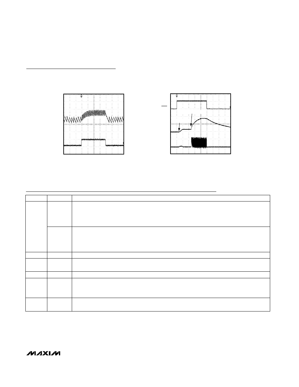
LOAD TRANSIENT
MAX8570/71/73/74/75 toc15
100
µs/div
V
OUT
I
OUT
100mV/div
(AC-COUPLED)
5mA/div
0
STARTUP AND SHUTDOWN WAVEFORMS
MAX8570/71/73/74/75 toc16
400
µs/div
V
OUT
I
LX
5V/div
10V/div
200mA/div
1.8
Ω LOAD
0
0
V
SHDN
BOOST SOFT-START
SW TURN-ON
Typical Operating Characteristics (continued)
(MAX8571, V
CC
= 3.6V, V
OUT
= 18V, Circuit of Figure 2, T
A
= +25
°C, unless otherwise noted.)