Applications information, Chip information, Table 3. output code vs. temperature – Rainbow Electronics MAX6662 User Manual
Page 8
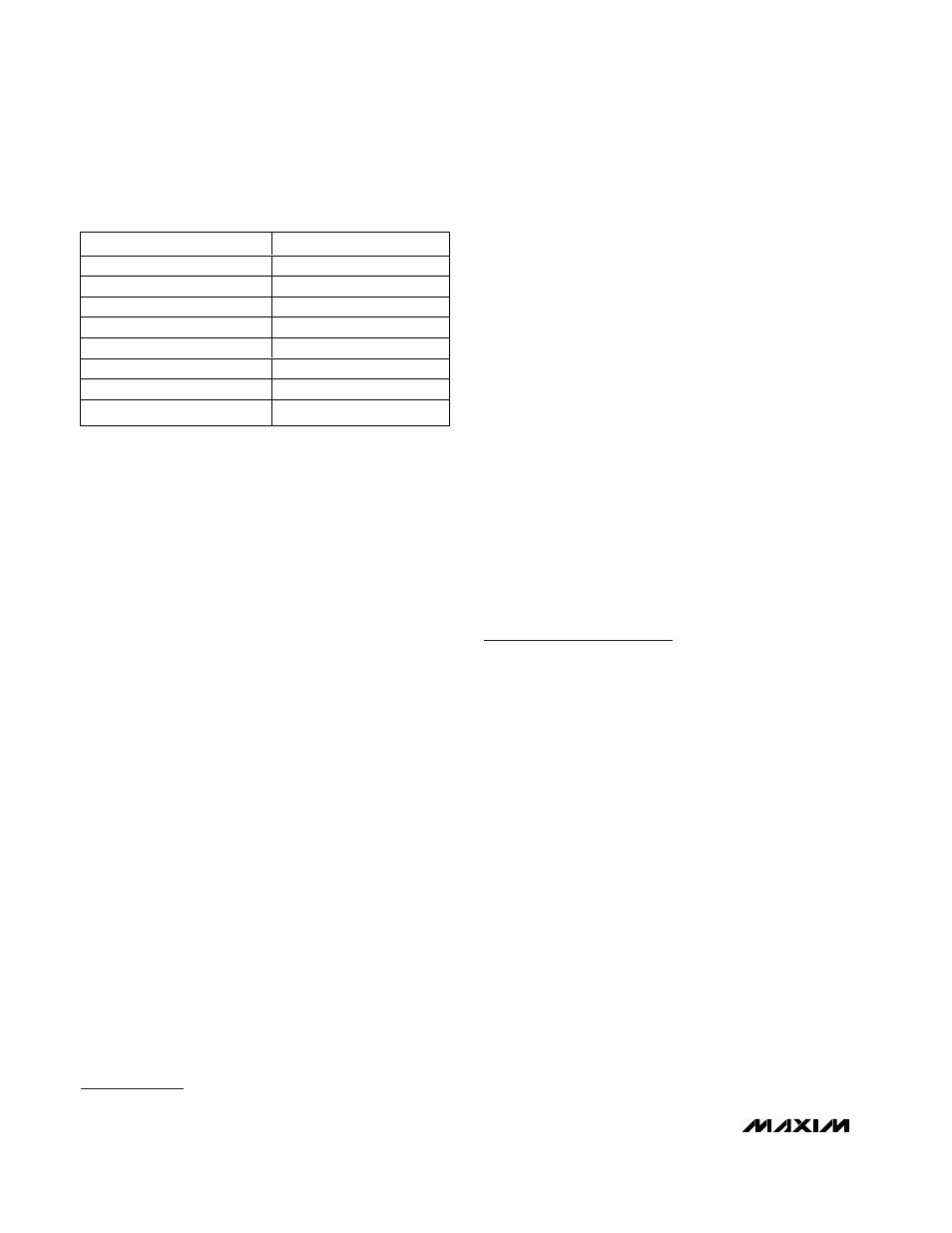
stored in the Temperature register and is in °C, using a
two’s-complement format with 1LSB corresponding to
0.0625°C (Table 3). The three least-significant bits (LSBs)
are temperature status (flag) bits. The Temperature regis-
ter is read only. Set the command byte to C1h for reading
the Temperature register.
Configuration Register
The Configuration register uses only 5 bits, bits 8 to 12.
Table 1 describes its function. Bit 8 is the shutdown bit
and should be set to 1 to shut down the entire
MAX6662 except the serial interface and POR. Bit 12 is
the fault queue bit. When the Fault Queue bit is 1, the
ALERT and OT outputs are asserted if four consecutive
temperature faults occurred. The Configuration register
can be read or written to. Writing to unused bits is
ignored. Set the command byte to C3h for reading from
this register; set the command byte to 83h for writing to
this register.
Temperature-Limit Registers
The High-Temperature (T
HIGH
), Low-Temperature
(T
LOW
), and the Hysteresis (T
HYST
) registers set the
temperature limit for triggering the
ALERT (Figure 1).
The Maximum-Temperature (T
MAX
) and Hysteresis reg-
isters set the temperature threshold for the
OT output.
These temperature-limit registers use the 9MSB bits
(8 bits + sign) for setting temperature values in two’s
complement format with 1°C resolution. The 7LSBs are
ignored. These registers can be read or written to.
Table 2 shows the command bytes for reading and
writing to these registers.
Applications Information
The MAX6662 supply current is typically 125µA when
the serial interface is active. When driving high-imped-
ance loads, the devices dissipate negligible power;
therefore, the die temperature is essentially the same
as the package temperature. The key to accurate tem-
perature monitoring is good thermal contact between
the MAX6662 package and the monitored device or cir-
cuit. Heat flows in and out of plastic packages primarily
through the leads. Short, wide copper traces leading to
the temperature monitor ensure that heat transfers
quickly and reliably. The rise in die temperature due to
self-heating is given by the following formula:
∆T
J
= P
DISSIPATION
x
θ
JA
where P
DISSIPATION
is the power dissipated by the
MAX6662, and
θ
JA
is the package’s thermal resistance.
The typical thermal resistance is +170°C/W for the
8-pin SO package. To limit the effects of self-heating,
minimize the output currents. For example, if the
MAX6662 sinks 4mA with the maximum
ALERT voltage
specification of 0.8V, an additional 3.2mW of power is
dissipated within the IC. This corresponds to a 0.54°C
rise in the die temperature.
Chip Information
TRANSISTOR COUNT: Bipolar: 182
MOS: 10177
PROCESS: BiCMOS
MAX6662
12-Bit + Sign Temperature Sensor with
SPI-Compatible Serial Interface
8
_______________________________________________________________________________________
TEMPERATURE (
°C)
BINARY CODE
+150.0000
0100 1011 0000 0xxx
+125.0000
0011 1110 1000 0xxx
+25.0000
0000 1100 1000 0xxx
+0.0625
0000 0000 0000 1xxx
0.0000
0000 0000 0000 0xxx
-0.0625
1111 1111 1111 1xxx
-25.0000
1111 0011 0111 0xxx
-55.0000
1111 1100 0111 0xxx
Table 3. Output Code vs. Temperature