Rainbow Electronics W78C438C User Manual
Page 7
W78C438C
Publication Release Date: July 1998
- 7 -
Revision A1
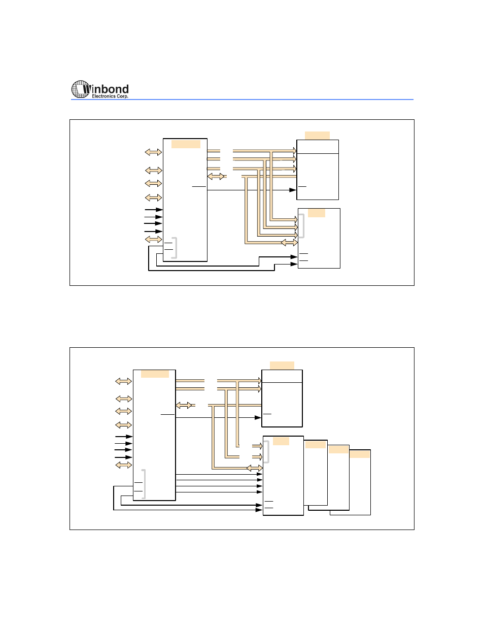
(A) EPMA.7 = 0
W78C438
EPROM
RAM
AP5
PSEN
ADDR 1MB
(20-bit)
ADDR (20-bit)
DATA
AP6
DP4
WR
RD
P3
OE
WE
OE
AP7
P1
P0
P2
P8
INT1
INT3
INT0
INT2
\ 8
\ 4
\ 8
\ 8
64K PROGRAM
DATA AREA
When bit 7 of the EPMA is "1," AP7<3:0> are the output pins that support memory-mapped peripheral
chip select logic, which eliminates the need for glue logic. These pins are decoded by AP6<7:6>.
Only one pin is active low at any time. That is, they are active individually with 16K address
resolution. For example, CS0 is active low in the address range from 0000H to 3FFFH, CS1 is active
low in the address range from 4000H to 7FFFH, and so forth.
(B) EPMA.7 = 1
W78C438
AP5
PSEN
AP6
DP4
WR
RD
P3
P1
P0
P2
P8
INT1
INT3
INT0
INT2
RAM
ADDR (14-bit)
DATA
WE
OE
AP7.0
AP7.1
AP7.2
AP7.3
0000h
3FFFh
4000h
7FFFh
8000h
BFFFh
C000h
FFFFh
\ 8
\ 8
\ 6
\ 8
\ 8
Device
Device
Device
(16k)
(16k)
(16k)
(16k)
EPROM
OE
64K PROGRAM
DATA AREA
ADDR (16-bit)
- MAX5151 (16 pages)
- MAXQ3108 (64 pages)
- MAX5661 (39 pages)
- MAX6691 (7 pages)
- MAX5362 (12 pages)
- ADC10158 (26 pages)
- MAX8922L (14 pages)
- MAX8596Z (8 pages)
- MAX7491 (18 pages)
- MAX15040 (15 pages)
- MAX5177 (16 pages)
- ADC08138 (22 pages)
- MAX5961 (42 pages)
- T89C51RD2 (86 pages)
- MAX16055 (9 pages)
- MAX6659 (17 pages)
- ADC0820 (20 pages)
- MAX6678 (19 pages)
- MAX8884Z (15 pages)
- MAX16915 (9 pages)
- MAX8620 (18 pages)
- MAX5144 (12 pages)
- MAX6670 (8 pages)
- MAX8760 (39 pages)
- W78C32C (14 pages)
- MX7533 (8 pages)
- MAX8727 (13 pages)
- MAX9053 (15 pages)
- W78C54 (16 pages)
- MAX8614B (15 pages)
- W90N740 (219 pages)
- MAX6626 (13 pages)
- ADC10738 (30 pages)
- MAX17000 (31 pages)
- MAX5051 (21 pages)
- MAXQ1004 (18 pages)
- MAX6871 (51 pages)
- MX7847 (12 pages)
- MAX6608 (6 pages)
- MAX17083 (15 pages)
- MAX6641 (17 pages)
- MAX5251 (16 pages)
- MAX6338 (8 pages)
- MAX6690 (16 pages)
- MAX8668 (18 pages)