Pin description, Typical operating characteristics (continued) – Rainbow Electronics MAX7407 User Manual
Page 8
Pin Description
PIN
Common Input. Biased internally at midsupply. Bypass externally to GND with a 0.1µF capacitor. To over-
ride internal biasing, drive with an external supply.
COM
1
FUNCTION
NAME
Filter Input
IN
2
Positive Supply Input: +5V for MAX7400/MAX7403, +3V for MAX7404/MAX7407
V
DD
4
Ground
GND
3
Offset Adjust Input. To adjust output offset, bias OS externally. Connect OS to COM if no offset adjustment is
needed. Refer to
Offset and Common-Mode Input Adjustment
section.
OS
6
Clock Input. To override the internal oscillator, connect to an external clock; otherwise, connect an external
capacitor (C
OSC
) from CLK to GND to set the internal oscillator frequency.
CLK
8
Shutdown Input. Drive low to enable shutdown mode; drive high or connect to V
DD
for normal operation.
SHDN
7
Filter Output
OUT
5
MAX7400/MAX7403/MAX7404/MAX7407
8th-Order, Lowpass, Elliptic,
Switched-Capacitor Filters
8
_______________________________________________________________________________________
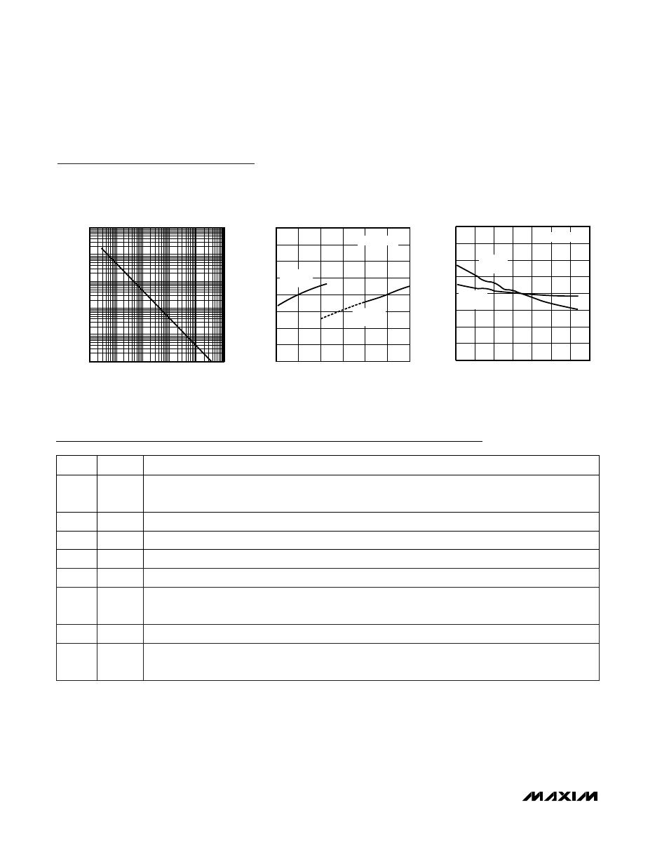
Typical Operating Characteristics (continued)
(V
DD
= +5V for MAX7400/MAX7403, V
DD
= +3V for MAX7404/MAX7407; V
COM
= V
OS
= V
DD
/ 2; SHDN = V
DD
; f
CLK
= 100kHz;
T
A
= +25°C; unless otherwise noted.)
0.96
0.98
0.97
1.00
0.99
1.03
1.02
1.01
1.04
-40
0
-20
20
40
60
80
100
NORMALIZED OSCILLATOR FREQUENCY
vs. TEMPERATURE
MAX7400 toC21
TEMPERATURE (°C)
NORMALIZED OSCILLATOR FREQUENCY
C
OSC
= 390pF
MAX7400
MAX7403
MAX7404
MAX7407
0.80
0.85
0.90
0.95
1.00
1.05
1.10
1.15
1.20
2.5
3.5
3.0
4.0
4.5
5.0
5.5
NORMALIZED OSCILLATOR FREQUENCY
vs. SUPPLY VOLTAGE
MAX7400 toc20
SUPPLY VOLTAGE (V)
NORMALIZED OSCILLATOR FREQUENCY
C
OSC
= 390pF
MAX7400
MAX7403
MAX7404
MAX7407
0.1
1
100
10
1000
10,000
0.01
1
0.1
10
100
1000
INTERNAL OSCILLATOR FREQUENCY
vs. C
OSC
CAPACITANCE
MAX7400 toc19
C
OSC
CAPACITANCE (nF)
OSCILLATOR FREQUENCY (kHz)