Pin description – Rainbow Electronics MAX5969B User Manual
Page 7
IEEE 802.3af/at-Compliant, Powered Device Interface
Controllers with
Integrated Power MOSFET
MAX5969A/MAX5969B
_______________________________________________________________________________________ 7
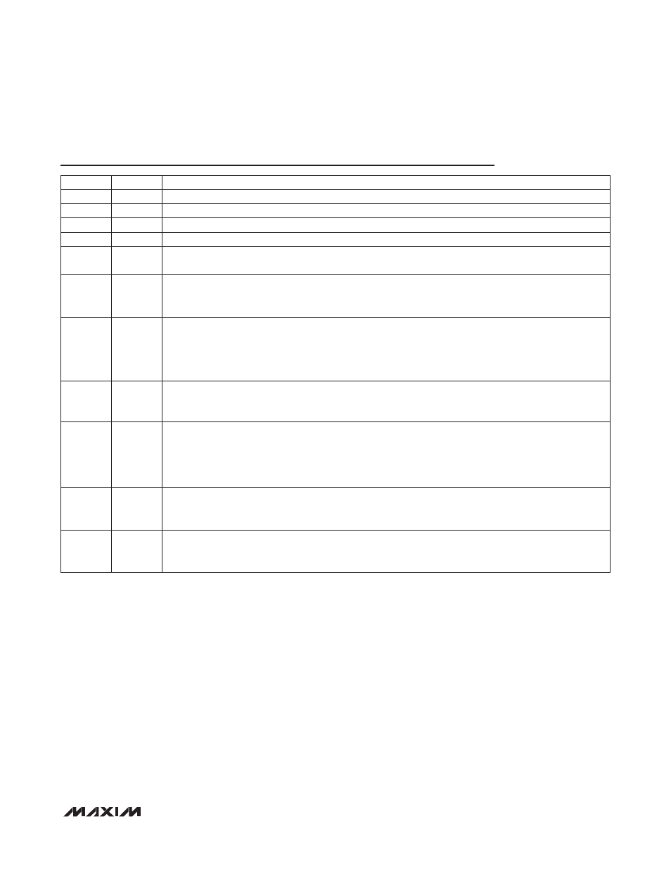
Pin Description
PIN
NAME
FUNCTION
1
V
DD
Positive Supply Input. Connect a 68nF (min) bypass capacitor between V
DD
and V
SS
.
2
DET
Detection Resistor Input. Connect a signature resistor (R
DET
= 24.9kI) from DET to V
DD
.
3
N.C.
No Connection. Not internally connected.
4
I.C.
Internally Connected. Leave unconnected.
5
V
SS
Negative Supply Input. V
SS
connects to the source of the integrated isolation n-channel power
MOSFET.
6
RTN
Drain of Isolation MOSFET. RTN connects to the drain of the integrated isolation n-channel power
MOSFET. Connect RTN to the downstream DC-DC converter ground as shown in the Typical
Application Circuit.
7
WAD
Wall Power Adapter Detector Input. Wall adapter detection is enabled the moment V
DD
- V
SS
crosses
the mark event threshold. Detection occurs when the voltage from WAD to RTN is greater than 9V.
When a wall power adapter is present, the isolation n-channel power MOSFET turns off, 2EC current
sink turns on. Connect WAD directly to RTN when the wall power adapter or other auxiliary power
source is not used.
8
PG
Open-Drain Power-Good Indicator Output. PG sinks 230FA to disable the downstream DC-DC converter
while turning on the hot-swap MOSFET switch until the hot-swap switch is fully on. PG current sink is
disabled during detection, classification, and in the steady-state power mode.
9
2EC
Active-Low 2-Event Classification Detect or Wall Adapter Detect Output. A 1.5mA current sink is
enabled at 2EC when a Type 2 PSE or a wall adapter is detected. When powered by a Type 2 PSE, the
2EC current sink is enabled and latched low after the isolation MOSFET is fully on until V
IN
drops below
the UVLO threshold. 2EC also asserts when a wall adapter supply, typically greater than 9V, is applied
between WAD and RTN. 2EC is not latched if asserted by WAD.
10
CLS
Classification Resistor Input. Connect a resistor (R
CLS
) from CLS to V
SS
to set the desired classification
current. See the classification current specifications in the Electrical Characteristics table to find the resis-
tor value for a particular PD classification.
––
EP
Exposed Pad. Do not use EP as an electrical connection to V
SS
. EP is internally connected to V
SS
through a resistive path and must be connected to V
SS
externally. To optimize power dissipation, solder
the exposed pad to a large copper power plane.