Applications information – Rainbow Electronics MAX5969B User Manual
Page 12
IEEE 802.3af/at-Compliant, Powered Device Interface
Controllers with
Integrated Power MOSFET
MAX5969A/MAX5969B
12 _____________________________________________________________________________________
Applications Information
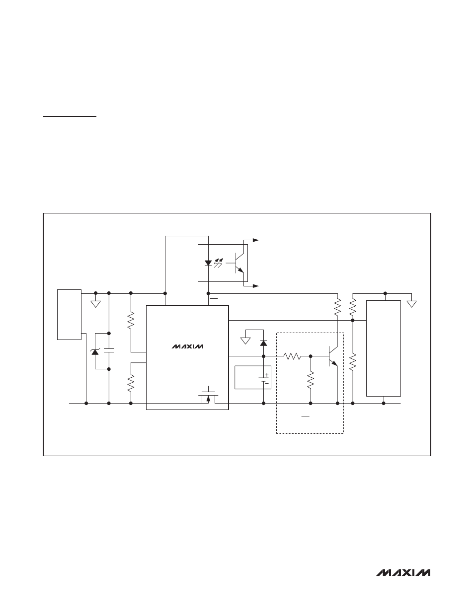
Operation with 12V Adapter
Layout Procedure
Careful PCB layout is critical to achieve high efficiency
and low EMI. Follow these layout guidelines for optimum
performance:
1) Place the input capacitor, classification resistor, and
transient voltage suppressor as close as possible to
the MAX5969A/MAX5969B.
2) Use large SMT component pads for power dissipat-
ing devices such as the MAX5969A/MAX5969B and
the external diodes.
3) Use short and wide traces for high-power paths.
4) Use the MAX5969 Evaluation Kit layout as a refer-
ence.
Figure 2. Typical Configuration When Using a 12V Wall Power Adapter
68nF
2-EVENT
CLASSIFICATION
(ASSERTED ON)
ENABLE
DC-DC
CONVERTER
IN+
IN-
RJ-45
AND
BRIDGE
RECTIFIER
GND
GND
-54V
SMAJ58A
MAX5969A
MAX5969B
R
DET
24.9kI
R
CLS
V
DD
V
SS
RTN
WAD
PG
DET
CLS
2EC
12V
BATTERY
THIS CIRCUIT ACHIEVES
PROPER 2EC LOGIC WHEN
BATTERY IS < 12.5V