Chip information, Table 8. conversion-rate control byte, Table 9. slave address decoding (add0 and add1) – Rainbow Electronics MAX6690 User Manual
Page 15
Power-Up Defaults:
• Interrupt latch is cleared.
• Address select pins are sampled.
• ADC begins autoconverting at a 0.25Hz rate.
• Command byte is set to 00h to facilitate quick
remote Receive Byte queries.
• T
HIGH
and T
LOW
registers are set to max and min
limits, respectively.
MAX6690
2°C Accurate Remote/Local Temperature
Sensor with SMBus Serial Interface
______________________________________________________________________________________
15
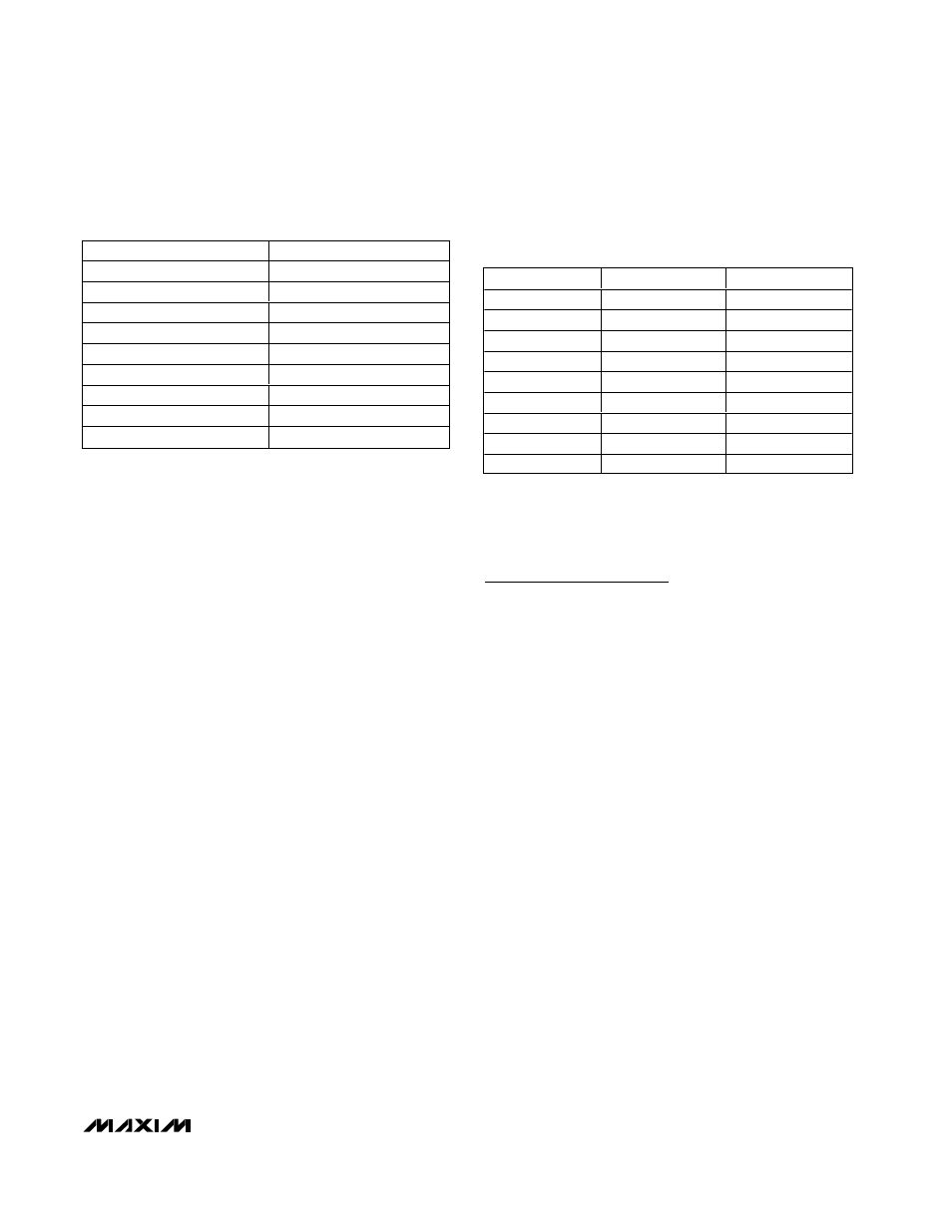
DATA
CONVERSION RATE (Hz)
00h
0.0625
01h
0.125
02h
0.25
03h
0.5
04h
1
05h
2
06h
4
07h
8
08h-FFh
Reserved
Table 8. Conversion-Rate Control Byte
ADD0
ADD1
ADDRESS
0
0
0011 000
0
High-Z
0011 001
0
1
0011 010
High-Z
0
0101 001
High-Z
High-Z
0101 010
High-Z
1
0101 011
1
0
1001 100
1
High-Z
1001 101
1
1
1001 110
Table 9. Slave Address Decoding (ADD0
and ADD1)
Note: High-Z means that the pin is left unconnected and floating.
Chip Information
TRANSISTOR COUNT: 12,504
PROCESS: BiCMOS