Typical operating characteristics (continued), Pin description – Rainbow Electronics MAX8614B User Manual
Page 8
MAX8614A/MAX8614B
Dual-Output (+ and -) DC-DC
Converters for CCD
8
_______________________________________________________________________________________
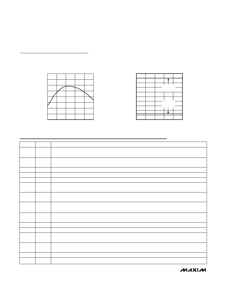
Typical Operating Characteristics (continued)
(T
A
= +25°C, V
CC
= V
AVCC
= 3.6V, SEQ = GND, Figure 1, unless otherwise noted.)
REFERENCE VOLTAGE
vs. TEMPERATURE
TEMPERATURE (
°C)
REFERENCE VOLTAGE (V)
MAX8614A/B toc21
-40
-15
10
35
60
85
1.2450
1.2455
1.2460
1.2465
1.2470
1.2475
1.2480
1.2485
1.2490
SWITCHING FREQUENCY
vs. TEMPERATURE
TEMPERATURE (
°C)
FREQUENCY (kHz)
MAX8614A/B toc22
-40
-15
10
35
60
85
0.996
0.997
0.998
0.999
1.000
1.001
1.002
1.003
1.004
1.005
1.006
V
BST
= +15V
I
OUT
= 50mA
V
INV
= -7.5V
I
OUT
= 100mA
PIN
NAME
FUNCTION
1
ONBST
Enable Logic Input. Connect ONBST to AV
CC
for automatic startup of the step-up converter, or use ONBST
as an independent control of the step-up converter.
2
FBN
Negative Output Feedback Input. Connect a resistor-divider between the negative output and REF with the
center to FBN to set the negative output voltage.
3
AV
CC
Bias Supply. AV
CC
powers the IC. AV
CC
must be connected to V
CC
.
4
REF
1.25V Reference Voltage Output. Bypass with a 0.22µF ceramic capacitor to GND.
5
GND
Ground. Connect GND to PGND with a short trace.
6
FLT
Fault Open-Drain Output. Connect a 100k
Ω resistor from FLT to AV
CC
. FLT is active low during a fault event
and is high impedance in shutdown.
7
FBP
Positive Output-Voltage Feedback Input. Connect a resistor-divider between the positive output and GND
with the center to FBP to set the positive output voltage. FBP is high impedance in shutdown.
8
SEQ
Sequence Logic Input. When SEQ = low, power-on sequence can be independently controlled by ONBST
and ONINV. When SEQ = high, the positive output powers up before the negative output.
9
ONINV
Enable Logic Input. Connect ONINV to AV
CC
for automatic startup of the inverter, or use ONINV as an
independent control of the inverter.
10
LXP
Positive Output Switching Inductor Node. LXP is high impedance in shutdown.
11
PGND
Power Ground. Connect PGND to GND with a short trace.
12
PVP
True-Shutdown Load Disconnect Switch. Connect one side of the inductor to PVP and the other side to LXP.
PVP is high impedance in shutdown.
13
V
CC
Power Input Supply. VCC supplies power for the step-up and inverting DC-DC converters. V
CC
must be
connected to AV
CC
.
14
LXN
Negative Output Switching Inductor Node. LXN is high impedance in shutdown.
—
EP
Exposed Pad. Connect exposed paddle to ground.
Pin Description