High-efficiency, 32v step-up converters with t, Derating option for 2 to 8 white leds, Detailed description – Rainbow Electronics MAX8596Z User Manual
Page 6
MAX8595Z/MAX8596Z
Detailed Description
The high efficiency and small size of the MAX8595Z/
MAX8596Z make them ideally suited to drive up to 8
series-connected LEDs. These devices operate as a
boost DC-DC converter that regulates output current
rather than voltage. The MAX8595Z/MAX8596Z provide
even illumination by sourcing the same output current
through each LED, eliminating the need for expensive
factory calibration. The fast 1MHz internal oscillator
allows for a small inductor and small input and output
capacitors while minimizing input and output ripple.
The single analog control input (CTRL) allows easy
adjustment of LED brightness and on/off control. This
allows simple logic-level on/off control, analog voltage
control, or PWM duty-cycle control of both brightness
and shutdown. In shutdown, supply current is reduced
to a low 0.3µA (typ). A soft-start gradually illuminates
the LEDs, eliminating the inrush current during startup.
The MAX8596Z has the additional feature of derating
LED current as ambient temperature rises. Above
+42
°C, the CS regulation voltage is reduced at a rate of
5.5mV/
°C, thus reducing the LED current.
Soft-Start
The MAX8595Z/MAX8596Z attain soft-start by charging
C
COMP
gradually with a current source. When V
COMP
rises above 1.25V, the internal MOSFET begins switch-
ing at a reduced duty cycle. When V
COMP
rises above
2.25V, the duty cycle is at its maximum. See the
Typical Operating Characteristics for an example of
soft-start operation.
Shutdown
The MAX8595Z/MAX8596Z enter shutdown when V
CTRL
is less than 100mV for more than 8.2ms. In shutdown,
supply current is reduced to 0.3µA (typ) by powering
down the entire IC except for the CTRL voltage-detec-
tion circuitry. C
COMP
is discharged during shutdown,
allowing the device to re-initiate soft-start when it is
enabled. Although the internal n-channel MOSFET does
not switch in shutdown, there is still a DC current path
between the input and the LEDs through the inductor
and Schottky diode. The minimum forward voltage of the
LED array must exceed the maximum input voltage to
ensure that the LEDs remain off in shutdown. However,
with 2 or more LEDs, the forward voltage is large
enough to keep leakage current low, less than 1µA
(typ). Typical shutdown timing characteristics are shown
in the Typical Operating Characteristics.
Overvoltage Protection
Overvoltage lockout (OVLO) occurs when V
OUT
is
above 34V (typ). The protection circuitry stops the inter-
nal MOSFET from switching and causes V
COMP
to
decay towards 0V. The device comes out of OVLO and
into soft-start when V
OUT
falls below 32V (typ).
Ambient Temperature Derating Function
(MAX8596Z)
The MAX8596Z limits the maximum LED current
depending on the die temperature. V
CS
is limited to
343mV up to +42
°C. Once the temperature reaches
+42
°C, the maximum V
CS
declines by 5.5mV/
°C until
the minimum 106.5mV threshold is reached at +85
°C.
Due to the package’s exposed paddle, the die temper-
ature is always very close to the PC board temperature.
The temperature derating function allows the LED cur-
rent to be safely set higher at normal operating temper-
atures, thereby allowing either a brighter display or
fewer LEDs to be used for normal display brightness.
See the Typical Operating Characteristics for LED
Current vs. Ambient Temperature.
High-Efficiency, 32V Step-Up Converters
with T
A
Derating Option for 2 to 8 White LEDs
6
_______________________________________________________________________________________
0.1
µF
PWM
CONTROL
IN
2.2
µF
22
µH
LX
PGND
OVER-
VOLTAGE
PROTECT
g
m
CS
SHUTDOWN
8.2ms
GND
COMP
CTRL
170mV
100k
Ω
121k
Ω
279k
Ω
1.25V CLAMP OR
TEMP DERATE CLAMP
R
SENSE
13
Ω
2.6V TO 5.5V
f
OSC
1MHz
0.1
µF
ANALOG
OR DIRECT
PWM
DIMMING
OUT
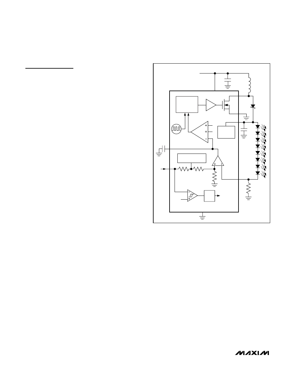
Figure 1. Functional Diagram and Typical Application Circuit