Banks Power Ford Motorhomes: (Gas ’97 - 05 6.8L V-10, Class-A (20-valve)) Power Systems- PowerPack, Stinger & Git-Kit Systems, (Class-A) '97-05 User Manual
Page 8
tube to allow the tube to be positioned
properly.
16.
Make sure the O-ring is on the
dipstick tube, and reinstall it into the
hole in the engine block. Reattach the
dipstick tube bracket to the cylinder
head with the new, longer bolt and
spacer supplied. Reattach the bracket
at the radiator core support with the
original hardware and put the dipstick
back in.
17.
If additional clearance at the front
of the right side TorqueTube manifold
for the air conditioning hose is needed,
very gently bend the line away from
the manifold until there is a minimum
of
3
⁄
4
” of clearance. Do not use a pry
bar or other tool to bend it as this
may damage the line. Wrap the air
conditioning line with the aluminum
heat shielding blanket provided, and
tie it with the supplied wire ties.
18.
If it was removed, reinstall the
crossmember at the front of the
vehicle.
19.
Place the new catalytic converter
flange gasket onto the studs on the
catalytic converter flange. Install the
Y-pipe onto the catalytic converter
using the original hardware, and the
pin hanger into the rubber hanger
on the frame of the vehicle. Place
a conical seal into the flare at the
forward end of the Y-pipe, and
attach the Y-pipe to the right side
TorqueTube manifold using the
3
⁄
8
” x
1
3
⁄
4
” bolts and washers provided. Do
not tighten the bolts yet.
20.
Slip a 2
1
⁄
2
” muffler clamp over
the free end of the Y-pipe, and then
slide the Y-pipe extension into the slip
joint. With the slip joint fully seated,
mark the extension pipe with a pen
so that as the clamp is tightened, any
slippage of the joint can be observed.
Place the second conical seal onto
the flare on the extension, and attach
the extension pipe to the left side
TorqueTube with the
3
⁄
8
” x 1
3
⁄
4
” bolts
and washers provided. Tighten the
2
1
⁄
2
” clamp at the slip joint, observing
the mark to be sure the joint stays
fully seated as the clamp is tightened.
Up to
1
⁄
4
” slip is acceptable. Tighten
the bolts at the manifold collectors.
21.
Install and tighten the oxygen
sensors into the threaded bungs
provided on the Y-pipe and extension.
Use a small amount of anti seize on
the threads of the oxygen sensors. Be
careful to not get any anti-seize on the
sensor elements themselves.
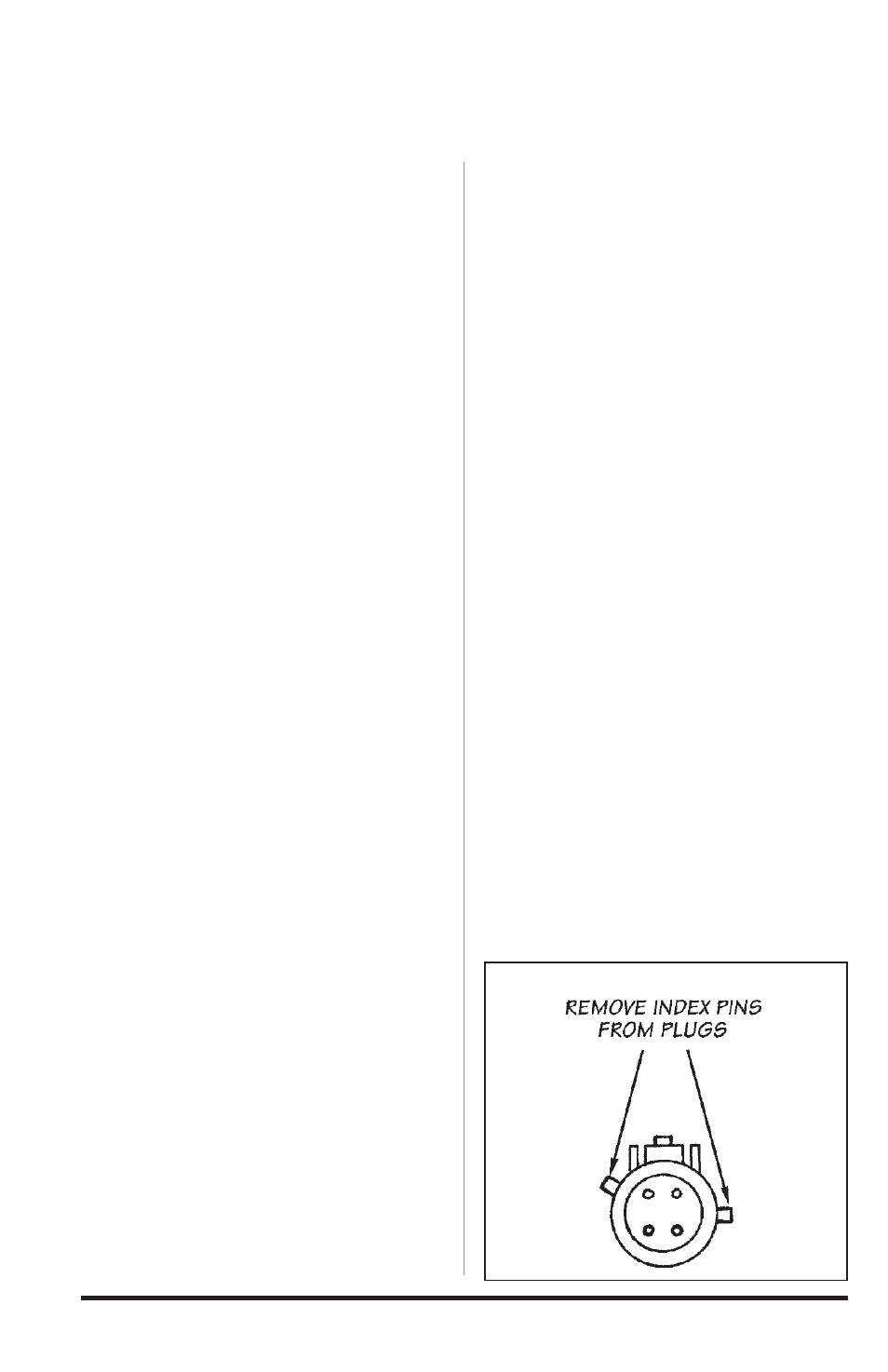
22.
On the connector on the oxygen
sensor and on the male connector on
the sensor extension lead, remove the
two index pins on the connector shell,
by cutting or filing. Be careful to not
damage the locking mechanism of the
connectors. see
figure 4.
23.
Plug the oxygen sensor extension
leads included in the kit into the
wiring harness where each sensor
was previously connected, then plug
the sensor lead into the extension.
Secure the leads away from any pipes
or moving linkages with the cable ties
provided.
-end, section 1-
Figure 4
8
96378 v.6.0