Banks Power Ford Motorhomes: (Gas ’97 - 04 6.8L Class-C) Power Systems- PowerPack & Stinger Systems & Optional OttoMind (Class-C) User Manual
Page 8
11.
Locate a wire connector block
mounted on a bracket on the left side
frame rail. This connector must be
relocated to allow clearance for the
left side TorqueTube. Unbolt the wire
connector from the bracket and roll it
around to mount on top of the frame
rail. Secure the connector to the frame
rail using the tie wraps provided. Wrap
the wires and connector with the heat
shield blanket provided and secure
with the wire ties.
12.
Disconnect the positive cable
from the starter. Remove the starter
from the vehicle.
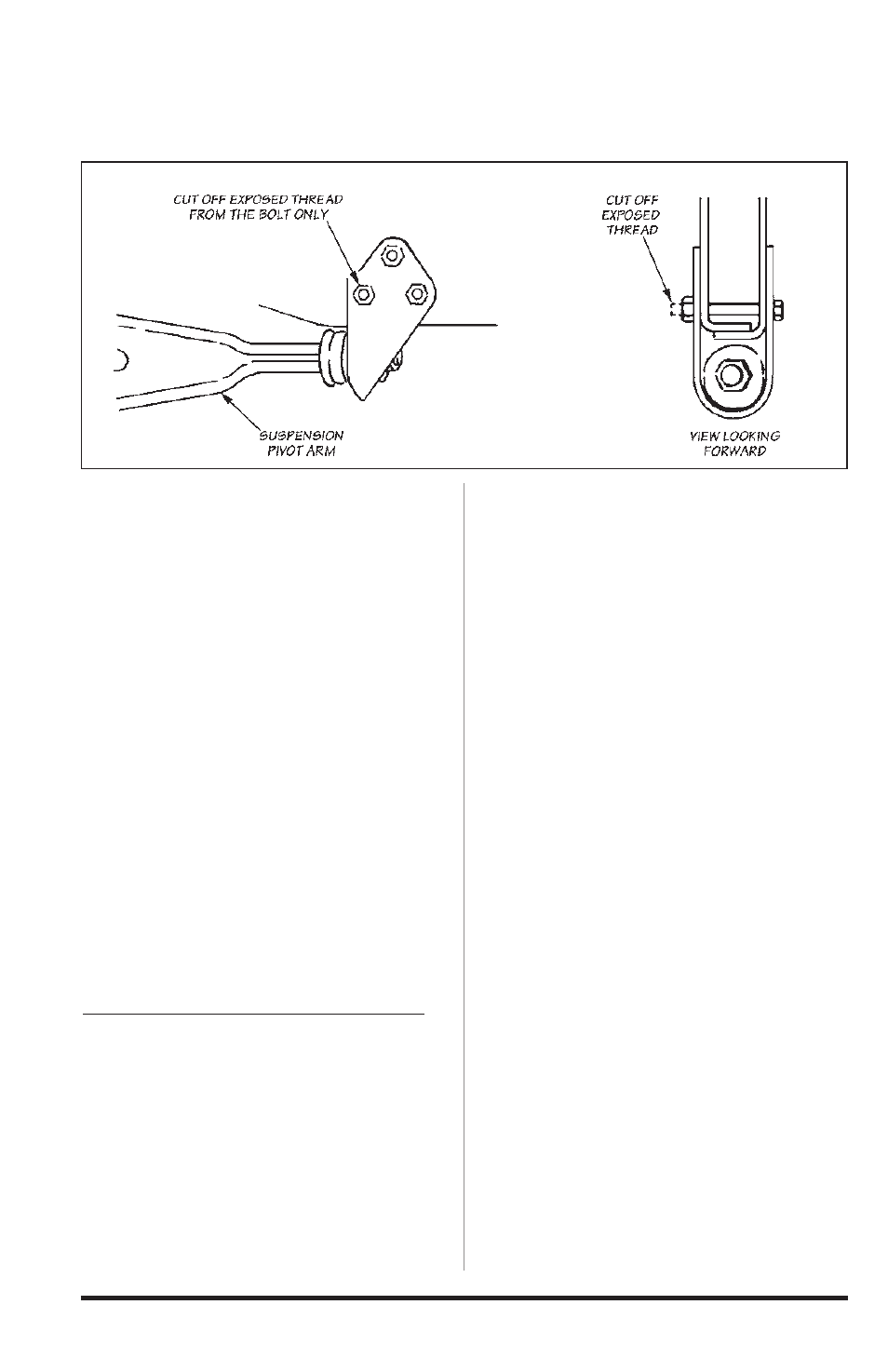
13.
On the passenger side of the
vehicle, cut off all excess thread
protruding thru the nut on the forward
bolt attaching the suspension pivot
arm to the frame as shown in
Figure 3.
Banks Torque Tube Installation
14.
Inspect the exhaust mounting
surfaces of the cylinder heads
and clean away any deposits to
assure proper sealing of the Banks
TorqueTubes. Be careful when doing
this as the cylinder heads are made
from aluminum, and can be easily
damaged. We recommend the use of a
Scotchbrite
®
pad.
15.
Place a small amount of anti-seize
on the threads of each of the supplied
manifold bolts. Use the new gaskets
provided when installing TorqueTubes.
Lift the Banks TorqueTube manifolds
into place and install one or two bolts
to hold them in position.
16.
Attach the EGR tube to
the adapter fitting in the Banks
TorqueTube manifold. If necessary,
loosen the fitting at the top of the EGR
tube to allow the tube to be positioned
properly.
17.
Install the remaining bolts into the
heads and tighten.
18.
Reinstall the starter motor using
the factory fasteners. Route the starter
cable away from the manifold.
19.
Inspect the exhaust manifold
installation for any wiring, hoses, or
carpet padding/insulation that are
within 2-3 inches of the manifolds or
EGR tubes. Tie wires away from the
exhaust components as required.
Trim away any carpet padding within
2 inches of the EGR tubes or exhaust
components. On some models the oil
cooler hoses may contact the header
heatshield. Reposition the cooler
hoses away from the heatshield using
wire ties or by twisting the ends of the
hoses at the connection to the oil filter
base. See Figure 4.
Figure 3
8
96401 v.9.0